


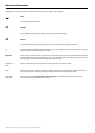
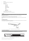
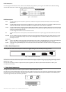
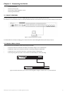

LED Indicators
The Switch supports LED indicators for Power,Master, Console, RPS,SIO (stacking indicators), a seven-segment Stack ID LED and Port LEDs.The following
sho
ws the LED indicators for the Switch along with an explanation of each indicator.
Figure 1- 3.LED Indicators
LED Description
Power This LED will light green after the Switch is powered on to indicate the ready state of the device.The indicator is dark when the Switch is
powered off.
Master This LED will light solid green when the Switch is configured to be a master switch of a switch stack in a ring topology or when it is in use as a
stand-alone switch.This LED will remain dark if the Switch is not configured to be a master switch in a switch stack.
Console This LED should blink during the Power-On Self Test (POST).When the POST is finished successfully, the LED goes dark.This indicator will light
solid green when the Switch is being logged into via out-of-band/local console management through the RS-232 console port in the front of the
Switch using a straight-through serial cable.
This LED will light solid amber if the Power-On-Self-Test has failed.
RPS This LED will be lit when the internal power has failed and the RPS has taken over the power supply to the Switch.Otherwise, it will remain
dark.
Port LEDs One row of LEDs for each port is located above the ports on the front panel.The first LED is for the top port and the second one is for the
bottom ports.A solid light denotes activity on the port while a blinking light indicates a valid link.These LEDs will remain dark if there is no
link/activity on the port.
Stacking Ports
(SIO) There are two LEDs in the front of the Switch marked SIO,and they relate to the two 10-gigabit stacking ports at the rear of the Switch.These
LEDs are marked 1 and 2 and will light solid green to denote activity on the port,while a blinking light will indicate a valid link.
Stack ID These two seven-segment LEDs display the current switch stack order of the Switch while in use.Possible numbers to be displayed range from
1-12 in use.
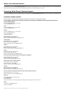
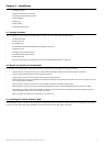
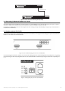
1-6 Rear Panel Components
The rear panel of the Switch contains an AC power connector,two 10-gigabit stacking ports and a redundant power supply connector.
Figur
e 1- 4.
Rear panel vie
w of the Switch
The
AC power connector is a standard three-pronged connector that supports the power cord.Plug-in the female connector of the provided power cord into
this socket,and the male side of the cord into a power outlet.The Switch automatically adjusts its power setting to any supply voltage in the range from 100 ~
240
V
A
C at 50 ~ 60 Hz.
The r
ear panel also includes an outlet f
or an optional external po
w
er suppl
y
.When power fails,the optional external RPS will take over all the power
immediately and automatically.
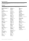
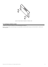
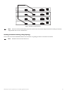
1-7 Side-P
a
nel Components
The right-hand side panel of the Switch contains 2 system fans,while the left hand panel includes a heat vent.
The system fans are used to dissipate heat.The sides of the system also provide heat vents to serve the same purpose.Do not block these openings,and leave at
least 6 inches of space at the r
ear and sides of the Switch f
or pr
oper v
entilation.
Be reminded that without proper heat dissipation and air circulation,system
components might overheat,which could lead to system failure.
Figure 1- 5.Side Panels
13
Allied Telesyn AT-9724TS High-Density Layer 3 Stackable Gigabit Ethernet Switch