


6-23 Layer 3 IP Networking
Lay
er 3 Global Advanced Settings
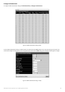
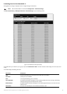
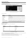
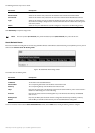
The L3 Global Advanced Settings window allows the user to enable and disable Layer 3 settings and functions from a single window.The full settings and
descriptions for these functions will appear later in this section.To view this window,open the
Configuration folder and then the Layer 3 IP Networking
folder and click on the L3 Global Advanced Settings link to access the following window.
Figure 6- 84.L3 Global Advanced Settings window
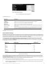
The user may set the following:
Parameter Description
DVMRP State
The user may globally enable or disable the Distance Vector Multicast Routing Protocol (DVMRP) function by
using the pull down menu.
PIM-DM State The user may globally enable or disable the Protocol Independent Multicast – Dense Mode (PIM-DM) function
by using the pull down menu.
RIP State The user may globally enable or disable the Routing Information Protocol (RIP) function by using the pull down
menu.
OSPF State The user may globally enable or disable the Open Shortest Path first (OSPF) function by using the pull down
menu.
ARP Aging Time (0-65535) The user may globally set the maximum amount of time,in minutes,that an Address Resolution Protocol (ARP)
entry can remain in the Switch’s ARP table,without being accessed,before it is dropped from the table.The
value may be set in the range of 0-65535 minutes with a default setting of 20 minutes.
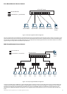
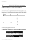
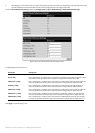
Setting Up IP Interfaces
Each VLAN must be configured prior to setting up the VLAN’s corresponding IP interface.
An example is presented below:
VLAN Name VID Switch Ports
System (default) 1 5,6,7, 8,21, 22,23, 24
Engineer 2 9, 10,11,12
Marketing 3 13,14,15,16
Finance 4 17, 18,19,20
Sales 5 1, 2,3,4
Backbone 6 25,26
T
able 6- 5.
VLAN Example –
Assigned P
or
ts
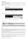
In this case
,
six IP interfaces ar
e r
equir
ed,so a CIDR notation of 10.32.0.0/11 (or a 11-bit) addressing scheme will work.This addressing scheme will give a subnet
mask of 11111111.11100000.00000000.00000000 (binary) or 255.224.0.0 (decimal).
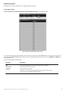
Using a 10.xxx.xxx.xxx IP address notation,the above example would give 6 network addresses and 6 subnets.
Any IP address from the allowed range of IP addresses for each subnet can be chosen as an IP address for an IP interface on the switch.
For this example,we have chosen the next IP address above the network address for the IP interface’s IP Address:
93
Allied Telesyn AT-9724TS High-Density Layer 3 Stackable Gigabit Ethernet Switch