


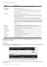
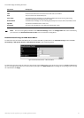
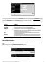
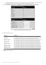
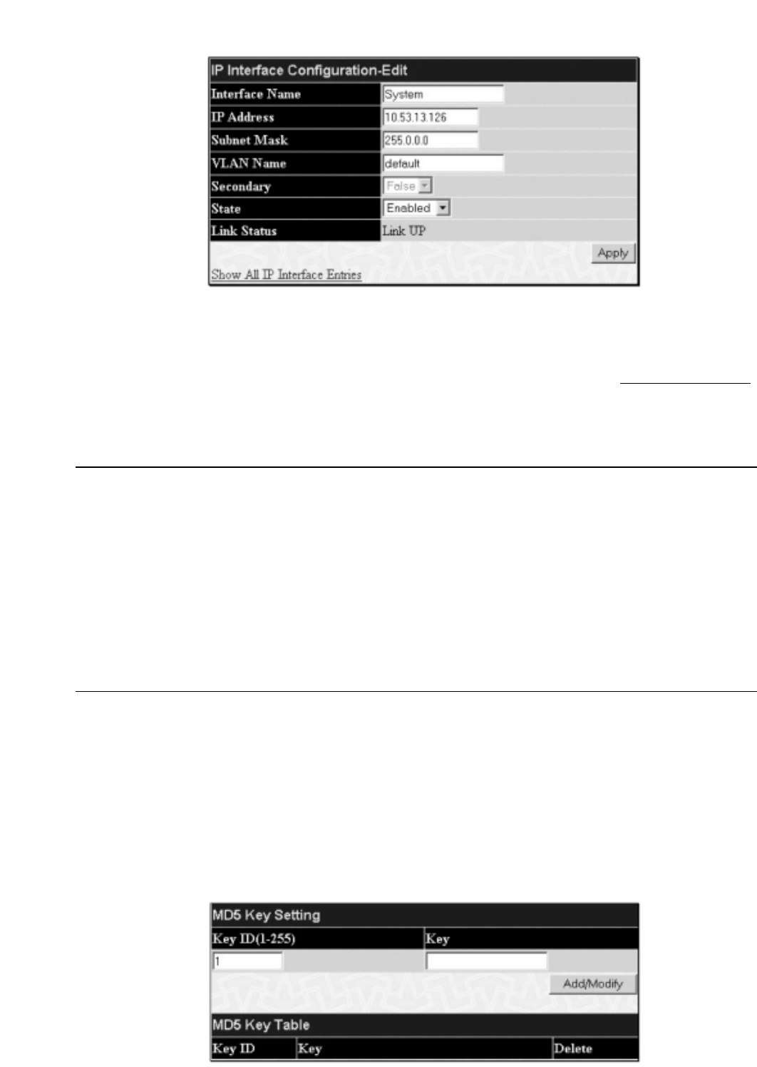
Figure 6- 87.IP Interface Configuration – Edit window
Choose a name for the interface to be added and enter it in the
Interface Name field (if you are editing an IP Interface,the Interface Name will already
be in the top field as seen in the window above).Enter the interface’s IP address and subnet mask in the corresponding fields.Pull the
State pull-down menu to
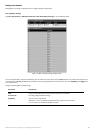
Enabled and click Apply to enter to make the IP interface effective.To view entries in the IP Interface Table,click the Show All IP Interface Entries
hyperlink.Use the Save Changes dialog box from the Maintenance folder to enter the changes into NV-RAM.
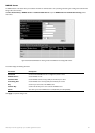
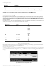
The following fields can be set:
Parameter Description
Interface Name
This field displays the name for the IP interface.The default IP interface is named “System”.
IP Address This field allows the entry of an IP address to be assigned to this IP interface.
Subnet Mask This field allows the entry of a subnet mask to be applied to this IP interface.
VLAN Name This field allows the entry of the VLAN Name for the VLAN the IP interface belongs to.
Secondary Use the pull-down menu to set the IP interface as True or False.True will set the interface as secondary and
False will denote the interface as the primary interface of the VLAN entered above.Secondary interfaces can
only be configured if a
primary interface is first configured.
State This field may be altered between Enabled and Disabled using the pull down menu.This entry determines
whether the interface will be active or not.
Link Status This read only field states the current status of the IP Interface on the Switch.Link Up denotes that the IP
interface is up and running on the Switch.Link Down will denote that the IP interface is not currently set
and/or enabled on the Switch.
Click
Apply to implement changes made.
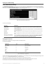
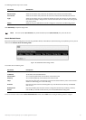
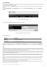
MD5 Key Table Configuration
The MD5 K
ey Table Configuration
men
u allows the entry of a sixteen-character Message Digest – version 5 (MD5) key which can be used to authenticate
e
v
er
y pack
et exchanged betw
een OSPF r
outers.
It is used as a security mechanism to limit the exchange of network topology information to the OSPF routing
domain.
MD5 Keys created here can be used in the
OSPF Interface Configuration menu below.
T
o configur
e an
MD5 K
ey
,
click the
MD5 K
ey
link to open the f
ollo
wing dialog bo
x:
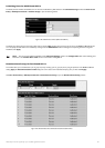
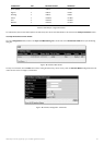
Figur
e 6- 88.MD5 Key Setting and Table window
95
Allied Telesyn AT-9724TS High-Density Layer 3 Stackable Gigabit Ethernet Switch