


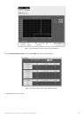
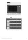
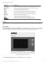
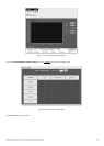
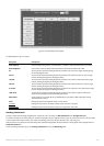
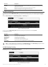

Figure 9- 14.Rx Size Analysis window (table)
The following fields can be set or viewed:
Parameter Description
Time Interval
Select the desired setting between 1s and 60s,where "s" stands for seconds.The default value is one second.
Record Number Select number of times the Switch will be polled between 20 and 200.The default value is 200.
64 The total number of packets (including bad packets) received that were 64 octets in length (excluding framing
bits but including FCS octets).
65-127 The total number of packets (including bad packets) received that were between 65 and 127 octets in length
inclusive (excluding framing bits but including FCS octets).
128-255 The total number of packets (including bad packets) received that were between 128 and 255 octets in length
inclusive (excluding framing bits but including FCS octets).
256-511 The total number of packets (including bad packets) received that were between 256 and 511 octets in length
inclusiv
e (excluding framing bits but including FCS octets).
512-1023 The total number of packets (including bad packets) received that were between 512 and 1023 octets in length
inclusiv
e (excluding framing bits but including FCS octets).
1024-1518 The total number of packets (including bad packets) received that were between 1024 and 1518 octets in
length inclusiv
e (excluding framing bits but including FCS octets).
Show/Hide Check whether or not to display 64,65-127,128-255, 256-511,512-1023, and 1024 1518 packets received
1024-1518 pack
ets r
eceiv
ed.
Clea
r
Clicking this button clears all statistics counters on this windo
w
.
Vie
w Table Clicking this button instructs the Switch to display a table rather than a line graph.
View Line Chart Clicking this button instructs the Switch to display a line graph rather than a table.
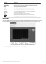
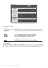
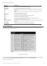
Stacking Information
To change a switch’s default stacking configuration (for example, the order in the stack),see Box Information in the Configuration folder.
The number of switches in the switch stack (up to 12 total) are displayed in the upper right-hand corner of your web-browser.The icons are in the same order
as their r
espectiv
e Unit n
umbers,
with the Unit 1 s
witch cor
responding to the icon in the upper left-most corner of the icon group.
When the switches are properly interconnected through their optional Stacking Modules,information about the resulting switch stack is displayed under the
Stack Information link.
To view the stacking information,click on the S
tacking Information link from the Monitoring folder:
166
Allied Telesyn AT-9724TS High-Density Layer 3 Stackable Gigabit Ethernet Switch