


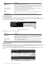
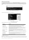
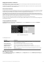

OSPF Virtual Interface Settings
Click the OSPF Virtual Interface Settings link to view the current OSPF Virtual Interface Settings.There are not virtual interface settings
configured by default,so the first time this table is viewed there will be not interfaces listed.To add a new OSPF virtual interface configuration set to the table,
click the
Add button.A new menu appears (see below).To change an existing configuration, click on the hyperlinked Transit Area ID for the set you want to
change.The menu to modify an existing set is the same as the menu used to add a new one.To eliminate an existing configuration,click the
✘ in the Delete
column.
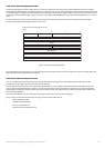
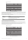
Figure 6- 116.OSPF Virtual Interface Settings window
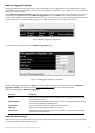
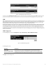
The status of the virtual interface appears (Up or Down) in the
Status column.
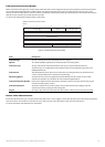
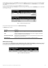
Figure 6- 117.OSPF Virtual Link Setting – Add
Configure the following parameters if you are adding or changing an
OSPF Virtual Interface:
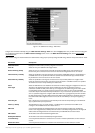
Parameter Description
T
r
a
nsit Ar
ea ID
Allo
ws the entr
y of an OSPF
Ar
ea ID – pr
e
viously defined on the Switch – that allows a remote area to
communicate with the backbone (area 0).A Transit Area cannot be a Stub Area or a Backbone Area.
Neighbor Router The OSPF router ID for the remote router.This is a 32-bit number in the form of an IP address
(xxx.xxx.xxx.xxx) that uniquely identifies the remote area’s Area Border Router.
Hello Interval (1-65535) Specify the interval between the transmission of OSPF Hello packets,in seconds.Enter a value between 1 and
65535 seconds.The Hello Interval,Dead Interval,Authorization Type,and Authorization Key should have
identical settings f
or all r
outers on the same netw
ork.
Dead Interval (1-65535) Specify the length of time between (receiving) Hello packets from a neighbor router before the selected area
declar
es that r
outer do
wn.Again,all routers on the network should use the same setting.
A
uth T
ype
If using authorization f
or OSPF r
outers,
select the type being used.MD5 key authorization must be set up in
the MD5 K
e
y Settings men
u.
Password/Auth. Key ID Enter a case-sensitive password for simple authorization or enter the MD5 key you set in the MD5 Key settings
menu.
T
r
a
nsmit Delay
The n
umber of seconds r
equir
ed to transmit a link state update o
v
er this virtual link.Transit delay takes into
account transmission and propagation delays.This field is fixed at 1 second.
R
etransInterval
The n
umber of seconds between link state advertisement retransmissions for adjacencies belonging to this
virtual link.This field is fixed at 5 seconds.
Click
Apply to implement changes made
.
Note: For OSPF to function pr
operl
y some settings should be identical on all par
ticipating OSPF de
vices.
These settings include the Hello Interval
and Dead Inter
val.
For networks using authorization for OSPF devices,the Authorization Type and Password or Key used must likewise be identical.
120
Allied Telesyn AT-9724TS High-Density Layer 3 Stackable Gigabit Ethernet Switch