


14
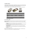
2.3.2 Removing a GBIC
Caution: GBIC 1000T modules run hot under normal operating conditions. When it has been removed from
the system, place it on a heat-resistant surface and allow the module to cool before handling.
Note: Unnecessary removals/insertions of a GBIC module will lead to premature failure of the GBIC. The
rated duty cycle for a GBIC module is 100 to 500 removals/insertions.
Follow the steps below to remove a GBIC interface from a Gigabit Ethernet module:
1. Disconnect the cable from the GBIC module.
2. Release the GBIC from the slot by simultaneously squeezing the locking tabs on both sides of the
GBIC.
3. Slide the GBIC out of the slot.
4. Fiber GBIC modules: Install the rubber plugs in the GBIC optical bores, and place the GBIC in
protective packaging.
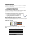
2.3.3 GBIC Care and Handling
Follow these GBIC maintenance guidelines:
• GBICs are static-sensitive. To prevent ESD damage, follow normal board and component handling
procedures. Wear an ESD wrist strap
• Fiber GBIC modules are very sensitive to dust and contaminants. When they are not connected to
a fiber-optic cable, install the rubber plugs in the optical bores
• The ferrules of the optical connectors may pick up debris that can obstruct the optical bore. Use an
alcohol swab or equivalent to clean the ferrules of the optical connector
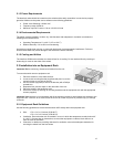
2.4 Installing the Optional Emergency Power Supply
To ensure increased reliability for mission-critical applications, the IC35160 can be equipped with a 12VDC
emergency backup power supply (the IC35-EPS12, sold separately). When installed, the emergency power
supply is in standby mode. Should the primary unit fail, the DC backup automatically switches on and the
LED on the front panel lights. In addition, an SNMP fault notice is sent.
Should the IC35-EPS12 become active due to a fault with the primary power, the unit should be swapped
out at the earliest convenience and sent for repair. The IC35-EPS12 is designed to be a temporary
replacement when the primary power fails, not a permanent replacement.
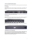
To install the optional power supply, simply attach the 12VDC connector of the power supply to the jack
located in the center of the rear panel of the switch. Connect the power cord to the power supply and plug
the power cord into an outlet.
Important! The optional power supply becomes HOT under normal operating conditions. To avoid damage
or injury, set the power supply on a heat-resistant surface and USE CAUTION when handling the unit.
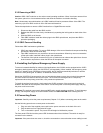
2.5 Connecting Power
Important: Carefully review the power requirements (Chapter 2.1.3) before connecting power to the switch.
Use the following procedure to connect power to the switch:
1. Plug one end of the supplied power cord into the power connector on the back of the unit.
2. Plug the other end into a grounded AC outlet.
3. Turn on the switch’s power. The power LED will begin its initialization process.
The front panel LEDs blink and the power LED illuminates when it has initialized. The switch is ready for
connection to the network.
Important: If the power does not come on, check the next section to ensure that the correct cabling is used.