Installation and Set-up
Page 2-12
Connecting to the Network
The IntraChassis 9000 unit may be connected to an Ethernet network, with the
unit powered either on or off. Use the following procedure to make your
network connections.
1 Connect network devices to the IntraChassis 9000, follow-
ing the cable guidelines outlined below.
2 Route the cables through the cable supports at the ends of
each module, to keep cables from the different modules
from interfering with each other.
3 After the unit is connected to the network, it can be config-
ured for management capabilities. See “Configuring for
Management” later in this chapter.
10/100BaseX Ports Cabling Procedures
The 24 fixed ports on each 10/100 module allow for the connection of 10Base-
T or 100Base-TX network devices. The ports are compatible with IEEE 802.3
and 802.3u standards.
▲ Important: The IntraChassis 9000 must be located
within 100 meters of its attached 10Base-T or 100Base-TX
devices.
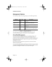
Table 2-2 10/100BaseTX cabling requirements
Connecting To Cable Required
Network Station Category 5 UTP (Unshielded Twisted-Pair) straight-through cable
(100 meters maximum) with RJ-45 connectors.
Repeater/Hub Category 5, UTP cross-over cable (100 meters maximum) with RJ-
45 connectors.
Repeater/Hub’s Uplink
port
Category 5, UTP straight-through cable (100 meters maximum)
with RJ-45 connectors.
GLXY9.book Page 12 Thursday, February 17, 2000 3:04 PM


