


3-2 Receiving & Installation MN1851
Electrical InstallationAll interconnection wires between the control, AC power source, motor, host
control and any operator interface stations should be in metal conduits. Use listed
closed loop connectors that are of appropriate size for wire gauge being used.
Connectors are to be installed using crimp tool specified by the manufacturer of
the connector. Only class 1 wiring should be used.
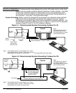
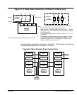
System Grounding Baldor controls are designed to be powered from standard single and three
phase lines that are electrically symmetrical with respect to ground. System
grounding is an important step in the overall installation to prevent problems. The
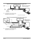
recommended grounding method is shown in Figure 3-1 and 3-3 for UL compliant
systems (Figure 3-2 and 3-4 for CE compliant systems).
Figure 3-1 Recommended System Grounding (3 phase) for UL
VL1
AC Main
Supply
Safety
Ground
Driven Earth
Ground Rod
(Plant Ground)
Four Wire
“Wye”
L1
L2
L3
Earth
L2 L3 UW
Route all power wires L1, L2, L3 and Earth
(Ground) together in conduit or cable.
Ground per NEC and Local codes.
Note:
Wiring shown for clarity of
grounding method only.
Not representative of actual
terminal block location.
Control
Note: Use shielded cable for control signal wires. Route
control signal wires in conduit. These wires must be
kept separate from power and motor wires.
PE
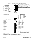
Figure 3-2 Recommended System Grounding (3 phase) for CE
VL1
AC Main
Supply
Four Wire
“Wye”
L1
L2
L3
L2 L3 UW
Route all power wires
L1, L2, L3 and Earth
(Ground) together in
conduit or cable.
Note:
Wiring shown for clarity of
grounding method only.
Not representative of actual
terminal block location.
Control
Note: Use shielded cable for control signal wires. Route
control signal wires in conduit. These wires must be
kept separate from power and motor wires.
PE
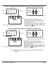
Enclosure Backplane (see Section 8)
Motor
GND
All shields
PE
Safety
Ground