


Receiving & Installation 3-7MN1851
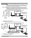
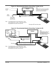
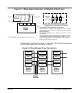
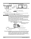
Figure 3-7 3 Phase Power Connections (LP2AxxS & LP4AxxT only)
L1 L2 L3
Alternate *
Fuse
Connection
Note 1
L1 L2 L3
L1 L2 L3
* Circuit
Breaker
Earth
* Components not provided with Control.
Note 2
Baldor
Control
Note 1
A1 B1 C1
Notes:
1. See Protection Device description in this section.
2. Metal conduit or shielded cable should be used. Connect
conduits so the use of a Reactor or RC Device does not interrupt
EMI/RFI shielding.
3. Use the same gauge wire for Earth as used for L1, L2, L3
connections.
3. Use same gauge wire for Earth ground as is used for L and N.
(VDE (Germany) requires 10mm
2
minimum, 6AWG). For CE
compliance, connect “PE” to the backplane of the enclosure.
4. Reference EMC wiring in Section 8.
Note 3 & 4
PE
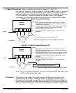
For CE Compliance, refer to Section 8 of this manual.
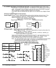
A shared supply configuration is shown in Figure 3-8. The first drive must have an
internal power supply such as an Option “S” control.
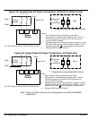
Figure 3-8 Shared Supply Power Connections
Baldor
Option S
Control
R2
R1
VCC-
VCC+
Baldor
Option P
Control
VCC-
VCC+
VCC-
VCC+
Baldor
Option P
Control
VCC-
VCC+
To
Regen
Resistor
VCC-
VCC+