


3-20 Receiving & Installation MN1851
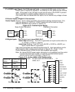
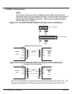
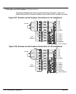
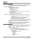
X9 Encoder and Hall Feedback (LPxAxxxx-Exxx)
Twisted pair shielded wire with an overall shield should be used. Figure 3-27
shows the electrical connections between the encoder and the encoder connector.
Figure 3-27 Encoder and Hall Feedback Connections for UL Installations
A+
A–
B+
B–
+5V
DGND
1
6
2
7
3
8
11
X9
Encoder
C+
C–
4
5
9
14
10
15
13
Shell (Chassis)
Hall 1+
Hall 1–
Hall 3+
Hall 3–
Hall 2+
Hall 2–
12 Not Used
Hall
Feedback
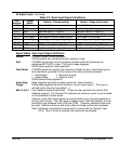
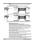
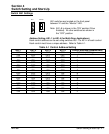
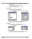
Figure 3-28 Encoder and Hall Feedback Connections for CE Installations
1
6
2
7
3
8
11
X9
Encoder
4
5
9
14
10
15
13
12
Hall
Feedback
A+
A–
B+
B–
+5V
DGND
C+
C–
Shell (Chassis)
Hall 1+
Hall 1–
Hall 3+
Hall 3–
Hall 2+
Hall 2–
Not Used