


A-6 Manual Tuning MN1851
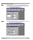
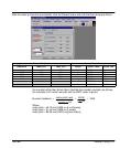
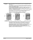
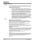
Manual Tuning The first six steps of the manual tuning process are shown in Figure A-16.
Figure A-16 Select Manual Tuning
Select
Tuning
Select Manual
Tuning
Select OK
1
2
3
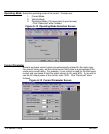
Select Pole
Placement
Enter either Inertia
or Inertia Ratio
(the other value is
automatically
entered).
Enter a value
for Bandwidth
4
5
6
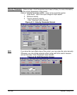
7
Click on
Download
If “Pole Placement” method of adjustment is selected, you would enter values for
“inertia” or “inertia ratio”. Enter either one, and the other value will automatically
be entered. This is the easiest and recommended method of adjustment.
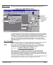
If “PI” method of adjustment is selected, you would enter values for GV–gain and
GVI–gain. This is an advanced method of adjustment, and is more difficult.
Both methods of adjustment provide identical results. PI method is described
later in this section.
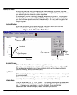
POLE PLACEMENT
Pole placement provides a “no–overshoot response” when tuned for the correct
inertia. This is the easiest and recommended method of adjustment.
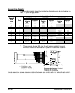
Inertia Click in the “Load” block and enter the value in Kg–cm
2
. The range is from
0 to 133 Kg–cm
2
. Pole placement tuning requires conversion of load mass
(weight) and motor mass (weight) values to inertia in Kg–cm
2
.
Kg * cm
2
+
ǒ
polepitch
2
x(motorlbs.) load lbs)
4p
2
Ǔ
100
Where: pole pitch (mm) LMBL=45.72; LMBLH=91.44; and LMCF=60.96.
If the inertia is under–estimated, the system will be stable. If the inertia is
over–estimated, the system will vibrate or oscillate due to too much system gain.
If the load inertia is unknown, estimate low. It is recommended to start with “load
inertia = 0.2”, which represents a stable condition.
If you entered the “inertia ratio”, you should enter a value representing the ratio of
reflected load inertia to motor inertia. The range is from 0 to 100.