


3-10 Receiving & Installation MN1851
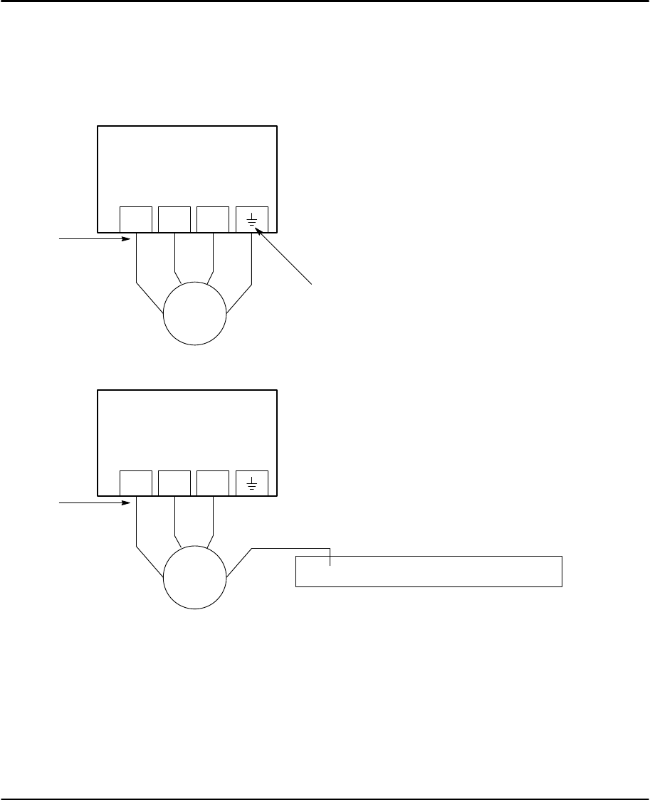
X1 Motor Connections Motor connections are shown in Figures 3-11 and 3-12.
It is important to connect the motor leads U, V and W correctly at the X1 connector
of the control. Incorrect wiring can cause erratic operation including moves at
peak force until the overcurrent limit trips. This will result in a display of “7” and a
“6” on the monitor. If erratic movement of the motor occurs, turn off power
immediately and check the connections of the motor, hall sensors and encoder.
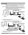
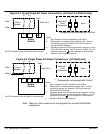
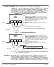
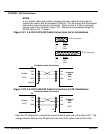
Figure 3-11 Motor Connections for UL
* Optional components not provided with control.
* Linear Motor
Baldor
Control
Note 1
UVW
U
VW
G
Notes:
1. Metal conduit or shielded cable should be used. Connect
conduits so the use of Load Reactor* or RC Device* does not
interrupt EMI/RFI shielding.
2. Use same gauge wire for Earth ground as is used for L and N.
(VDE (Germany) requires 10mm
2
minimum, 6AWG).
3. Reference EMC wiring in Section 8.
4. Motor and encoder are phase sensitive. Connect only as
instructed.
Note 2
For three phase controls, this is labeled “PE”.
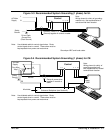
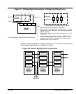
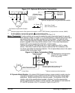
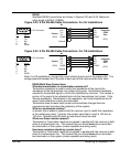
Figure 3-12 Motor Connections for CE
* Optional components not provided with control.
* Linear Motor
Baldor
Control
Note 1
UVW
U
VW
G
Notes:
1. Metal conduit or shielded cable should be used. Connect
conduits so the use of Load Reactor* or RC Device* does not
interrupt EMI/RFI shielding.
2. Use same gauge wire for Earth ground as is used for L and N.
(VDE (Germany) requires 10mm
2
minimum, 6AWG). For CE
compliance, connect motor ground to the backplane of the
enclosure.
3. Reference EMC wiring in Section 8.
4. Motor and encoder are phase sensitive. Connect only as
instructed.
Note 2
Enclosure Backplane (see Section 8)
Note: For CE compliant installations, connect unused leads within the motor cable
to “PE” on both ends of the cable.
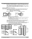
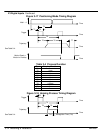
M-Contactor If required by local codes or for safety reasons, an M-Contactor (motor circuit
contactor) may be installed. However, incorrect installation or failure of the
M-contactor or wiring may damage the control. If an M-Contactor is installed, the
control must be disabled for at least 20msec before the M-Contactor is opened or
the control may be damaged. M-Contactor connections are shown in Figure 3-13.