


Section 4
Switch Setting and Start-Up
Switch Setting & Start-Up 4-1MN1851
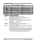
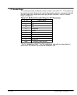
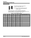
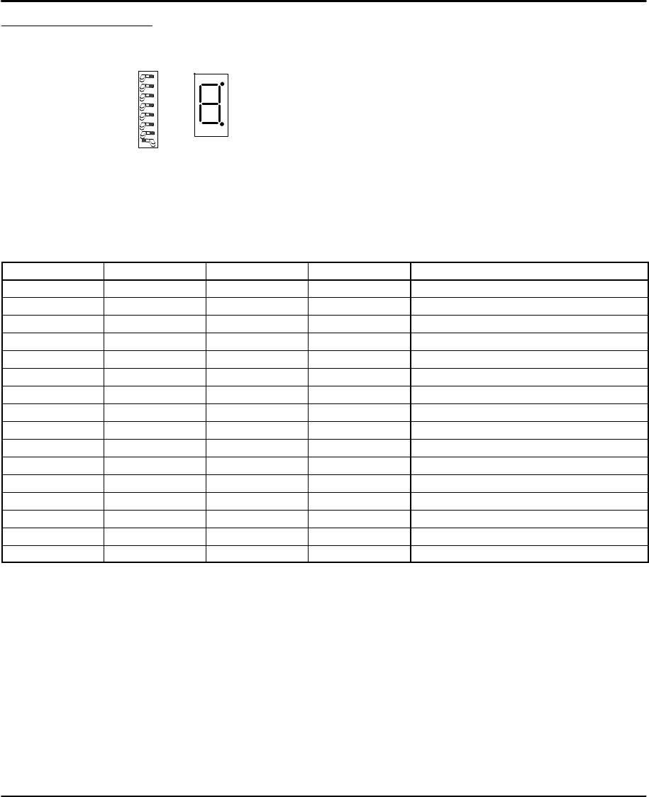
Switch AS1 Settings
Monitor
7
8
Off / On
AS1
6
5
4
3
2
1
Note: AS1–8 is shown in the “ON” position (Drive
Enabled). All other switches are shown in
the “OFF” position.
AS1 switches are located on the front panel
between X1 and the “Monitor” LED.
Address Setting, AS1-1 to AS1-4 (for Multi-Drop Applications)
Each control address can be set using switches AS1-1 to AS1-4 of each control.
Each control must have a unique address. Refer to Table 4-1.
Table 4-1 Control Address Setting
AS1-1 AS1-2 AS1-3 AS1-4 Control Address (Hexadecimal)
OFF OFF OFF OFF 0 (Factory Setting)
ON OFF OFF OFF 1
OFF ON OFF OFF 2
ON ON OFF OFF 3
OFF OFF ON OFF 4
ON OFF ON OFF 5
OFF ON ON OFF 6
ON ON ON OFF 7
OFF OFF OFF ON 8
ON OFF OFF ON 9
OFF ON OFF ON A
ON ON OFF ON B
OFF OFF ON ON C
ON OFF ON ON D
OFF ON ON ON E
ON ON ON ON F