


Receiving & Installation 3-15MN1851
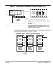
X3 Digital Outputs
The control outputs are located on the X3 connector. A customer provided,
external power supply must be used if digital outputs are to be used. The opto
outputs provide status information and are not required for operation, Table 3-5.
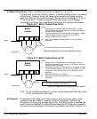
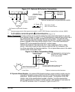
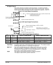
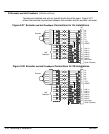
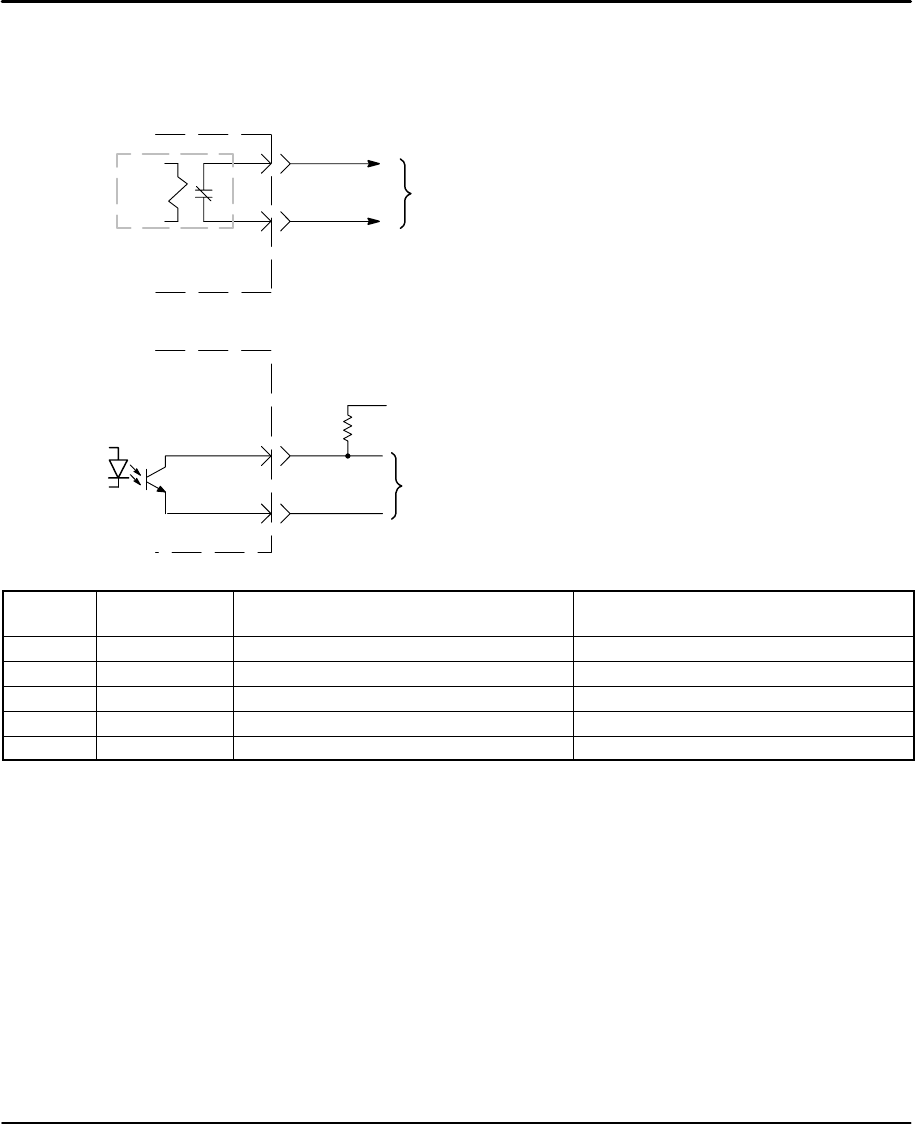
Figure 3-19 Fault Relay Connections
Control
4
5
Customer provided external power source: and Non-Inductive Load
110VAC @ 0.3A maximum or
24VDC @ 0.8A maximum
Relay
Customer Provided Interface Circuit
Contact is closed when power is on
and no faults are present.
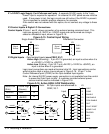
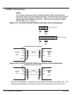
Figure 3-20 Opto Output Connections
Control Customer Provided Interface Circuit
18, 19, 20
Typical
8
Output Signal + Common
Customer Interface Voltage (+12VDC to +30VDC)
CGND
35mA Maximum
Output Signal is only available if
Customer Interface Voltage is present.
R
L
(2.2K typical @ 24VDC)
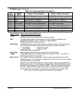
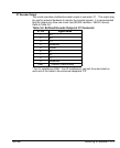
Table 3-5 Opto Output Signal Conditions
Pin
Number
Signal
Name
Switch = Closed (active) Switch = Open (not active)
X3-4 Fault + Drive OK - no faults detected Fault is detected
X3-5 Fault - Drive OK - no faults detected Fault is detected
X3-18 MAO1 Machine Output 1 = Logical 1 Machine Output 1 = Logical 0
X3-19 MAO2 Machine Output 2 = Logical 1 Machine Output 2 = Logical 0
X3-20 DrOK Drive OK - no faults detected Fault is detected
Fault Relay A normally closed relay contact that opens if a fault occurs. The contact is rated:
24VDC @ 0.8A maximum or 110VAC @ 0.3A maximum.
MaO1 & 2 Two machine outputs are provided. Either output can be set to one of the
following conditions: CW Warning, CCW Warning, In Position, Error Flag,
Following Error Warning, MAI1-2, Drive Overtemperature or I
2
T Warning.
Each output is rated 30VDC @ 35mA maximum.
DrOK This output is active when the control is ready for operation.
This output is rated 30VDC @ 35mA maximum.