


3-8 Receiving & Installation MN1851
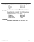
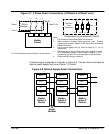
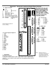
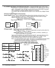
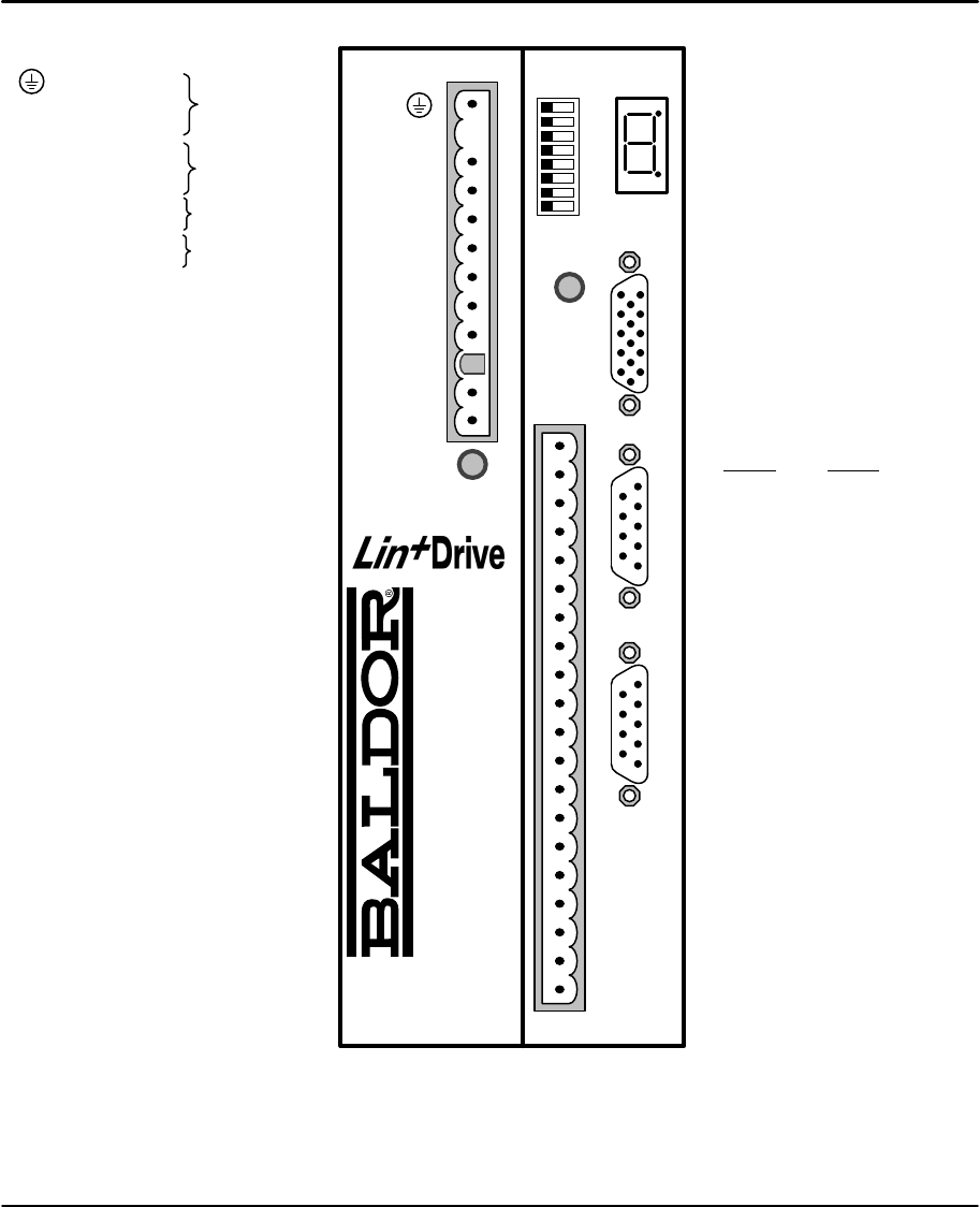
Figure 3-9 Connector Locations (Single Phase Controls)
X6 - RS232 / 485
RS232
RS485
1 Reserved 1 TX-
2R
x
Data 2 TX+
3T
x
Data 3 RX+
4 DTR 4 RX-
5 DGND 5 DGND
6 DSR 6 RTS-
7 RTS 7 RTS+
8 CTS 8 CTS+
9 +5V 9 CTS-
X3 - Control Signals & Digital I/O
1 CMD+
2 CMD-
3 AGND
4 Fault Relay+
5 Fault Relay-
6CIV
7 CREF
8 CGND
9 Enable
10 MaI3
11 MaI4
12 Quit
13 Fault Reset
14 Home Flag
15 Trigger
16 MaI1
17 MaI2
18 MaO1
19 MaO2
20 DrOK
X1 - Power Connector
Earth
L AC Line
N Neutral
U Motor lead “U”
V Motor lead “V”
W Motor lead “W”
R1 Dynamic Brake
R2 Dynamic Brake
+24V Customer
0V Provided
Dynamic Brake
(Regen Resistor)
Motor
Input Power
AS1
1
2
3
4
5
6
7
8
Off/On
Ready
X3
DB On
Encoder In X9RS232 / 485 X6Encoder Out X7
Monitor
X1
NC
N
L
U
V
W
R1
R2
+24V
0V
LPxAxxxx-xxx3
only
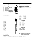
X7 - Encoder Output
1 CHA+ 6 CHA–
2 CHB+ 7 CHB–
3 CHC+ 8 CHC–
4 Reserved 9 Reserved
5 DGND
Important:
LPxAxxxx-xxx3 only.
A separate 24VDC supply to the “Logic Power” input is required for
operation. An LPxAxxxx-xxx3 control will not operate without 24VDC
on this input.
X9 - Encoder Input
1 CHA+ 9 Hall 3+
2 CHB+ 10 Hall 2+
3 CHC+ 11 +5VDC
4 Hall 1+ 12 Reserved
5 Hall 1– 13 DGND
6 CHA- 14 Hall 3–
7 CHB- 15 Hall 2–
8 CHC-
Note: Reserved means no
connection is required and
no connection should be
made to this terminal. It is
reserved for future use.
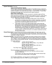
Terminal tightening torque is
0.5 lb-in (0.6Nm)
The holes in the top and
bottom of the enclosure
are for cable clamps. Be
sure to use an M4 bolt
12mm in length. Longer
bolts may short circuit the
electrical components
inside the control.