


Operation 5-11MN1851
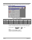
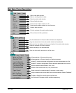
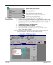
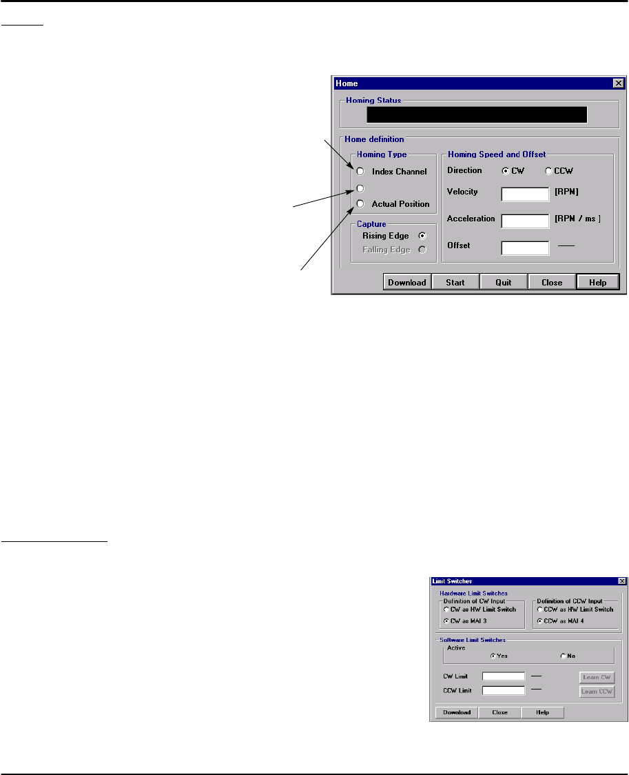
Home Starts a search for the machines absolute zero position. When home is found, the
control will hold the position at absolute zero. There are three Homing types:
Index channel, Capture and Actual Position.
Index Channel causes the motor shaft to rotate to a predefined
home position. The motor may rotate CW or CCW as specified
by the user. Home is located when a machine mounted switch is
activated, then the motor direction is reversed and continues until
the “0” position of the resolver is detected (or the “C” channel of
an encoder). The actual position of “Zero” relative to this point
can be set by the user by changing the offset value.
If home flag is active, clear absolute revolution counter at position
C. Set C (+ HOME.OFFSET) = Zero Position.
Brake with HOME.ACC to zero velocity. Move to Zero.
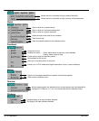
Capture
Actual position sets the Zero position to the current position.
No movement required.
Capture is a more accurate way to define home position.
The home flag captures the closure of the machine mounted
switch. This captured position (+ HOME.OFFSET) = Zero
Position.
Brake with HOME.ACC to zero velocity. Move back to Zero.
1
65536
Rev
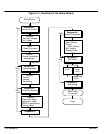
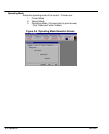
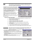
Procedure to define home position.
1. Be sure the machine mounted switch (Home position) is connected to X3 pin 14.
2. Select “Homing” from the Motion menu.
3. Choose the desired homing type.
4. Choose the desired capture edge (rising or falling).
5. Choose the desired home direction, CW or CCW.
6. Choose the desired home velocity, acceleration and offset parameters.
7. Click Download.
8. Click the Start button to begin the homing definition (Quit button to stop).
9. To start homing by hardware, buffer line 0 must be selected by MAI1–4.
10. To begin the home move, the external trigger must be present at input X3 pin 15.
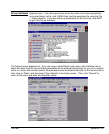
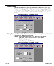
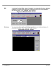
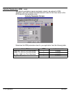
Limit Switches After Homing is set, the limit switches can be activated and set as desired. If the
inputs at X3–10 and X3–11 are used for machine inputs, software limits can be
used to sense when a position limit has been reached.
1. From the Main menu select “Setup ⇒ Limit Switches”.
2. Set “Hardware Limit Switches” as limits switches or as machine inputs.
3. Set the Software Limit Switches, “Active” to Yes or No. Yes activates a software
switch when the position exceeds a predefined limit. No deactivates the software
limit switch feature.
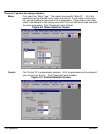
4. If software limit switches are set to Active = Yes, enter a position for the CW limit
and a position for the CW limit.
If you want to take the current absolute position as CW limit or CCW limit, click on
“Learn CW” or “Learn CCW”. The ”Learn” function only works after a successful
homing sequence.
5. Click ”Download” to send the parameters to the control.
Note: The value for the CW limit must be greater than the CCW limit value.
1
65536
Rev
1
65536
Rev