


3-12 Receiving & Installation MN1851
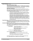
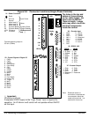
X1 +24VDC Logic Supply For LPxAxxxx-xxx3 only. A separate 24VDC supply to the “Logic
Power” input is required for operation. An external 24 VDC power source must be
used. If bus power is lost, the logic circuits are still active if the 24VDC is present.
This is important to maintain position reference, for example.
If the control was not ordered with this option, do not connect any voltage to these
pins.
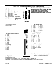
X3 Control Inputs & Digital I/O Connections
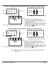
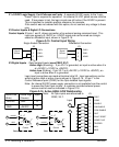
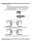
Control Inputs X3 pins 1 and 2 allows connection of an external analog command input. This
input can accept a 0-10VDC or ±10VDC signal and can be wired as a single
ended or differential input, shown in Figure 3-15.
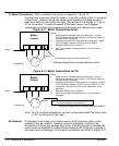
Figure 3-15 Control Input Wiring
CMD+
CMD-
AGND
X3
1
2
3
Single Ended Connection Differential Connection
Signal
Source
CMD+
CMD-
AGND
X3
1
2
3
Signal
Source
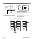
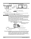
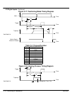
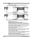
X3 Digital Inputs - Opto Isolated Inputs (uses CREF, X3-7)
Active High (Sourcing) - If pin X3-7 is grounded, an input is active when it is
at +24VDC (+12VDC to +30VDC).
Active Low (Sinking) - If pin X3-7 is at +24VDC (+12VDC to +30VDC), an
input is active when it is grounded.
Logic input connections are made at terminal strip X3. Input connections can be
wired as active High or active Low as shown in Figure 3-16. X3 pin 7 is the
Control Reference point (CREF) for the Opto Isolated Input signals.
Note: An internal 24VDC power supply connection is not available from the control
to power the Opto Input circuits. A customer provided external power
source must be used as indicated in Figure 3-16.
Figure 3-16 Active HIGH /LOW Relationship
Active Low
(Sink)
Active High
(Source)
+24VDC
GND
GND
+24VDC
MAI2
CREF
ENABLE
CW-ENABLE
CCW-ENABLE
QUIT
FAULT RESET
HOME FLAG
TRIGGER
X3
7
9
10
11
12
13
14
15
16
17
MAI1
CGND
8
A
B
Input
A
B
Input
Note: All Opto inputs are referenced to
CREF, X3-7.
9 - 17
Typical
7
Control
B
A
+24VDC
GND
Source
9 - 17
7
Control
B
A
GND
+24VDC
Sink
Typical
20mA 20mA