


12-6 BE-1204B-BC • BE-1206B-BC
Chapter 12 Troubleshooting
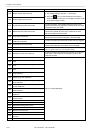
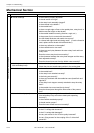
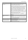
Symptom Measures
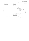
ERROR A8 frequently occurs. • In the encoder signal test mode, manually turn the main shaft pulley
and check to see that the stop position signal is correct.
→ If the signal does not change, refer to the cable connection block
diagram and check to see if connection from the stop position
sensor to the power supply PCB is proper.
Thread trimming motor home position
error occurs.
• Is lint clogged between the travelling blades?
→ Remove it.
• Is the thread trimming motor operating?
→ If so, refer to the block diagram showing the cable connections and
check to see if connection from the thread breakage sensor to the
main PCB is proper. Also adjust the thread breakage sensor PCB.
(Refer to "Replacing thread breakage sensor PCB.)
• If it is not operating, refer to the block diagram showing the cable
connections and check to see if connection from the thread trimming
motor to the main PCB is proper.
• Check to see if connection from connector P3 of the main PCB to
connector P9 of the power supply PCB in the control box is proper.
• Check fuse F6 on the power supply PCB in the control box.
→ If it is blown, replace it with a new one. If it is blown again, replace
the power supply PCB.
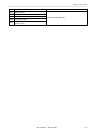
Power frequency error occurs. • Check whether the connector P2 of the power supply PCB is fallen out.
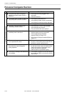
Wiper out error occurs. • Does the wiper on the error head remain projected?
→ If the wiper is tangled with a thread, remove it. If the wiper does
not return smoothly, adjust it.
• Enter the solenoid test mode and operate the wiper motor. Check the
icon on the panel.
→ If the icon is not reversed white, check to see if connection from the
wiper sensor to the head PCB is proper. Replace the wiper sensor
with a new one. Replace the head PCB with a new one.
Embroidering data buffer empty,
embroidering start error occurs.
NOTE
This error may rarely occur according
to your PC's performance.If it occurs,
check the items shown on the left.
• Has the IF cable come off?
• Has the RS cable on the PC come off?
• Is the PC or machine controller down?
→ Reboot the PC or machine controller.
• Are any other software programs running on the PC?
• Replace the IF cable.
Main shaft rotation speed error
occurs.
• Enter the encoder signal test mode and manually turn the main shaft
pulley.
→ If it is abnormally heavy, the main shaft mechanism is faulty.
• Refer to the block diagram showing the cable connections and check
to see if connection from the main shaft motor to the drive PCB is
proper.
Cooling fan motor stops.
Exhaust fan motor stops.
When all three fans in the control box
stop
• Refer to the block diagram showing the cable connections and check
to see if connection from connector P4 of the power PCB in the control
box to connector P3 and P4 of the drive PCB .
• Check fuse in the fuse holder at the side of the control box.
→ If it is blown, replace it with a new one.