


BE-1204B-BC • BE-1206B-BC 2-13
Chapter 2 Preparation of Embroidery Machine
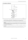
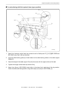
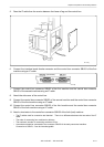
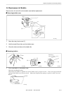
5. Pass the IF cable from the crevice between the frame of leg and the control box.
W1354Q
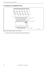
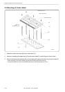
6. Connect the interface board female connector and the control box connector SBUS1 of the first
machine using an IF cable.
W1353Q
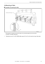
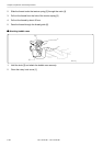
7. Connect the control box connector SBUS2 of the first machine and the control box connector
SBUS1 of the second machine using an IF cable.
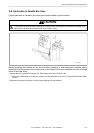
8. Attach the side cover of the control box.
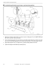
9. Connect the control box connector SBUS2 of the second machine and the control box connector
SBUS1 of the third machine using an IF cable.
10. Connect the control box connector SBUS2 of the third machine and the control box connector
SBUS1 of the forth machine using an IF cable.
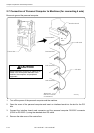
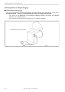
11. Attach a terminator to the control box connector SBUS2 of the forth (last) machine.
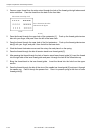
• The IF cables used for connection are identical. There is no difference between the two ends of the IF
cable.
• The order of connecting four machines is arbitrary.
• The maximum number of connecting machines is four.
• A terminator should be connected to the connector SBUS2 of the lastly connected machine.
Connection to SBUS1, 2 can be interchangeable.
(Terminator)