


BE-1204B-BC • BE-1206B-BC 12-7
Chapter 12 Troubleshooting
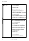
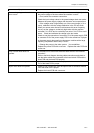
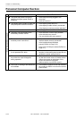
Symptom Measures
Power voltage upper or lower limit
error occurs.
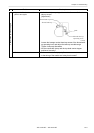
• Is the tap voltage in the control box (connector connection) adjusted to
the power voltage of the area where the machine is used?
→ If not, switch the connector connection.
• Check the input voltage values in the power/voltage check test mode.
Measure the power supply voltage with the tester and compare them.
→ If the voltage value is significantly out of the normal range (± 5v or
more), calibrate it with the voltage calibration in the PC test mode.
• When you cannot enter the test mode because this error frequently
occurs, set the voltage to a relatively high value with the machine
controller if it is E-D2 and to a relatively low value if it is E-D3 to avoid
errors. Check and calibrate the voltage in the test mode.
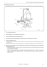
• Check to see the connection of connector P2 of the power supply PCB
to connector P10 of the power supply PCB in the control box is proper.
• Is the power supply abnormally low because a machine with a large
capacity (compressor and the like) is used?
→ Change the power to the other system. Use a stabilizer.
• Replace the power PCB with a new one. Replace the main PCB with
a new one.
Only a certain head does not
operate.
• Is the head out of action with either the head switch or the machine
controller?
• Refer to the block diagram showing cable connections and check to
see that other cables are connected to the head switch PCB and the
head PCB and the head PCB properly.
Jump motor does not operate. • Check to see if connection from the jump motor to connector P11 and
P12 of the head PCB is proper.
Wiper motor does not operate.
• Check to see if connection from the wiper motor to connector P8 and
P9 of the head PCB is proper.
• Replace the head PCB with a new one.