


1-4
Catalyst 2960 Switch Hardware Installation Guide
OL-7075-05
Chapter 1 Product Overview
Front Panel Description
Catalyst 2960-24-S, 2960-24TC-S, and 2960-48TC-S Switches
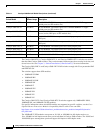
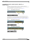
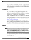
The 10/100 ports on the Catalyst 2960-24-S switch are numbered as follows: The first member of the
pair (port
1) is above the second member (port 2), port 3 is above port 4, and so on. See Figure 1-1.
Figure 1-1 Catalyst 2960-24-S Switch Front Panel
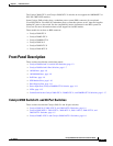
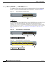
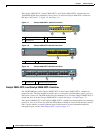
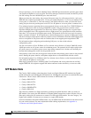
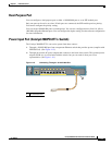
The 10/100 ports on the Catalyst 2960-24TC-S and Catalyst 2960-48TC-S switches are numbered in the
same way as the Catalyst 2960-24T-S switch. These switches have dual-purpose ports, that is,
10/100/1000 ports 1 and 2 can use either the SFP
module or the RJ-45 connector for that port, but not
both at the same time. Use the software to set the connector type for these ports. For more information
about the dual-purpose port, see the
“Dual-Purpose Port” section on page 1-11. See Figure 1-2 and
Figure 1-3.
Figure 1-2 Catalyst 2960-24TC-S Switch Front Panel
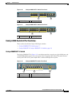
Figure 1-3 Catalyst 2960-48TC-S Switch Front Panel
1 10/100 ports
Catalyst 2960
Series SI
SYST
STAT
DUPLX
SPEED
MODE
1
191917
1 10/100 ports 2 Dual-purpose ports
Catalyst 2960
Series SI
SYST
STAT
DUPLX
SPEED
MODE
191916
2
1
1 10/100 ports 2 Dual-purpose ports
Catalyst 2960
Series SI
SYST
STAT
DUPLX
SPEED
MODE
1 2
191915
65 87 109 1211 21 43
1817 2019 2221 1413 1615
3029 3231 3433 3635 2625 2827
4241 4443 4645 4847 3837 4039
2423