


1-19
Catalyst 2960 Switch Hardware Installation Guide
OL-7075-05
Chapter 1 Product Overview
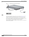
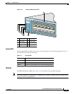
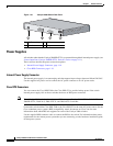
Rear Panel Description
Warning
Attach only the following Cisco RPS model to the RPS receptacle:
PWR-RPS2300, PWR675-AC-RPS-N1=.
Statement 370
For more information about the Cisco RPS 675, see the Cisco RPS 675 Redundant Power System
Hardware Installation Guide on Cisco.com.
Cisco RPS 2300 Connector
The Catalyst 2960-24PC-L and 2960-24LT-L switches support only the Cisco RPS 2300. This is a
redundant power system that can support six network switches and provide power to one or two failed
switches at a time. It automatically senses when the power supply of a connected switch fails and
provides power to the failed switch, preventing loss of network traffic.
The Cisco RPS 2300 has two output levels: –52 V and 12 V. The total maximum output power depends
on the installed power-supply modules.
The six ports on the RPS 2300 provide the power and management communication signals to the
Catalyst
2960 switches. The RPS 2300 communicates with the Catalyst 2960-24PC-L and
Catalyst
2960-24LT-L switches through the 22-pin cable (CAB-RPS2300-E=). All other Catalyst 2960
switches connect to the RPS 2300 through a 14-pin connector cable (CAB-RPS2300=).
All connected switches can simultaneously communicate with the RPS 2300. You can configure these
RPS 2300 features through the switch software:
• Enable RPS active or standby mode for each connected switch
• Configure switch priority for RPS support
• List the connected switches and their power-supply module size
• Obtain reports when a switch is powered by the RPS
• Obtain status reports for the RPS power-supply module
• Read and monitor backup, failure, and exception history
For more information about the RPS 2300, see the Cisco Redundant Power System 2300 Hardware
Installation Guide on Cisco.com at this location:
http://www.cisco.com/en/US/products/ps7148/products_installation_guide_book09186a008075e608.html
Also see the switch software configuration guide on Cisco.com.
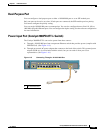
Console Port
You can connect the switch to a PC by means of the console port and the supplied RJ-45-to-DB-9 female
cable. If you want to connect the switch console port to a terminal, you need to provide an
RJ-45-to-DB-25 female DTE adapter. You can order a kit (part number ACS-DSBUASYN=) containing
that adapter from Cisco. For console port and adapter pinout information, see the
“Connector and Cable
Specifications” section on page A-1.