


3-16
Catalyst 2960 Switch Hardware Installation Guide
OL-7075-05
Chapter 3 Switch Installation (8-Port Switches)
Installing the Switch
Mounting the Switch in a 19-Inch Rack
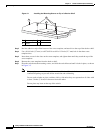
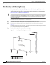
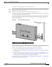
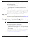
After the brackets are attached to the switch, insert the switch into the 19-inch rack, and align the bracket
in the rack. Use either the 10-32 pan-head screws or the 12-24 pan-slotted screws to secure the switch
in the rack, as shown in
Figure 3-9.
Note We strongly recommend that you allow at least 1.75 inches (4 cm) of clearance above each switch in
the rack.
Figure 3-9 Mounting the Switch in a 19-Inch Rack
After the switch is mounted in the rack, do these tasks to complete the installation:
1. Power on the switch. See the “Verifying Switch Operation” section on page 3-6.
2. Connect to a 10/100 or 10/100/1000 port, and run Express Setup. See the switch getting started guide
for instructions.
3. Connect to the front-panel ports. See the “Connecting to the 10/100 and 10/100/1000 Ports” section
on page 2-18, the “Connecting to SFP Modules” section on page 2-19, and the “Connecting to a
Dual-Purpose Port” section on page 2-22 to complete the installation.
For configuration instructions about using the CLI setup program, go to Appendix C, “Configuring the
Switch with the CLI-Based Setup Program.”
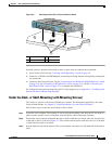
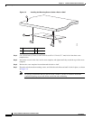
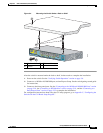
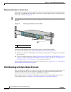
Wall-Mounting (with Rack-Mount Brackets)
To install the Catalyst 2960 8-port switches in a 19-inch rack requires an optional bracket kit that is not
included with the switch. You can order a kit containing the 19-inch rack-mounting brackets and
hardware from Cisco. The kit part number is RCKMNT-19-CMPCT=.
This section is specific to the Catalyst 2960 8-port switches. For information applicable to the other
Catalyst 2960 switches, see
Chapter 2, “Switch Installation (24- and 48-Port Switches).”
1 Phillips machine screws
2
x
3
x
4
x
5
x
6
x
7
x
8
x
1
Catalyst 2960
S
eries
C
O
N
S
O
L
E
1
x
S
P
D
D
P
L
X
S
T
A
T
S
Y
S
T
M
O
D
E
1
210100