


3-4
Catalyst 2960 Switch Hardware Installation Guide
OL-7075-05
Chapter 3 Switch Installation (8-Port Switches)
Preparing for Installation
• Humidity around the switch must not exceed 85 percent.
• Altitude at the installation site must not be greater than 10,000 feet (3,049 meters).
• The bottom of the switch might be hot to the touch if the switch is operating at its maximum
temperature 113°F (45°C) and is in an environment that exceeds normal room temperature (such as
in a closet, in a cabinet, or in a closed or multirack assembly).
• Do not place any items on the top of the switch.
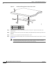
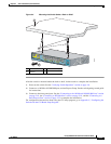
• Do not stack switches or place switches side-by-side unless they are separated on all sides by at least
3
inches (7.6 cm) of clearance from each other.
• Allow at least 1.75 inches (4 cm) of clearance above each switch in the rack.
• Do not wall-mount the switch with its front panel facing up or sideways. According to safety
regulations, wall-mount the switch with its front panel facing down to prevent airflow restriction and
to provide easier access to the cables.
• Clearance to the switch front and rear panels meets these conditions
–
You can easily read the front-panel indicators.
–
Access to ports is sufficient for unrestricted cabling.
–
The AC power cord can reach from the AC power outlet to the connector on the switch
rear
panel.
• Cabling is away from sources of electrical noise, such as radios, power lines, and fluorescent
lighting fixtures. Make sure the cabling is safely away from other devices that might damage the
cables.
• For 10/100/1000 ports, cable lengths from the switch to connected devices must be 328 feet
(100
meters).
• The cables meet the specifications in Table A-1 on page A-5, which lists the cable specifications for
1000BASE-X and 100BASE-X small form-factor (SFP) modules available for the Catalyst 2960
switch.
When you use shorter lengths of single-mode fiber-optic cable, you might need to insert an inline
optical attenuator in the link to avoid overloading the receiver.
When the fiber-optic cable span is less than 15.43 miles (25 km), you should insert a 5-decibel (dB)
or 10-dB inline optical attenuator between the fiber-optic cable plant and the receiving port on the
1000BASE-ZX SFP module at each end of the link.
Equipment That You Supply
This section is specific to the Catalyst 2960 8-port switches. For information applicable to the other
Catalyst 2960 switches, see
Chapter 2, “Switch Installation (24- and 48-Port Switches).”
You need this equipment to install the switch:
• Number-2 Phillips screwdriver
• Drill with a #27 drill bit (0.144-inch [3.7 mm])