


2-19
Catalyst 2960 Switch Hardware Installation Guide
OL-7075-05
Chapter 2 Switch Installation (24- and 48-Port Switches)
Connecting to SFP Modules
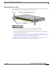
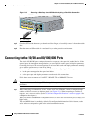
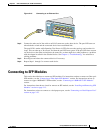
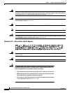
Figure 2-16 Connecting to an Ethernet Port
Step 2 Connect the other end of the cable to an RJ-45 connector on the other device. The port LED turns on
when both the switch and the connected device have established link.
The port LED is amber while Spanning Tree Protocol (STP) discovers the topology and searches for
loops. This can take up to 30 seconds, and then the port LED turns green. If the port LED does not turn
on, the device at the other end might not be turned on, or there might be a cable problem or a problem
with the adapter installed in the attached device. See
Chapter 4, “Troubleshooting,” for solutions to
cabling problems.
Step 3 Reconfigure and reboot the connected device if necessary.
Step 4 Repeat Steps 1 through 3 to connect each device.
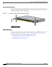
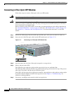
Connecting to SFP Modules
This section describes how to connect to SFP modules. For instructions on how to connect to fiber-optic
SFP modules, see the
“Connecting to Fiber-Optic SFP Modules” section. For instructions on how to
connect to copper 1000BASE-T SFP modules, see the “Connecting to 1000BASE-T SFP Modules”
section.
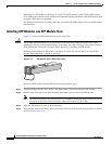
For instructions about how to install or remove an SFP module, see the “Installing and Removing SFP
Modules” section on page 2-15.
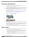
For instructions on how to connect to a dual-purpose port, see the “Connecting to a Dual-Purpose Port”
section on page 2-22.
SYST
RPS
STAT
DUPLX
SPEED
M
O
D
E
1
X
1
1
X
1
X
2
X
1
1
X
1
2
X
137086