2-8
Catalyst 2960 Switch Hardware Installation Guide
OL-7075-05
Chapter 2 Switch Installation (24- and 48-Port Switches)
Installing the Switch
Rack-Mounting
This section applies to all switches except the Catalyst 2960-8TC-L, Catalyst 2960G-8TC-L, and
Catalyst 2960PD-8TT-L switches. For information applicable to those switches, see
Chapter 3, “Switch
Installation (8-Port Switches).” The illustrations in this section might not show your specific switch;
however, the instructions apply to all 24- and 48-port switches.
To install the switch in a 19-inch or 24-inch rack (24-inch racks require optional mounting hardware),
follow the instructions described in these sections:
• Removing Screws from the Switch, page 2-8
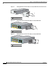
• Attaching Brackets to the Catalyst 2960 Switch, page 2-9
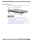
• Mounting the Switch in a Rack, page 2-11
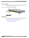
• Attaching the Cable Guide, page 2-12
An optional bracket kit that is not included with the switch is required to install the switch in a 24-inch
rack. You can order a kit that contains the 24-inch rack-mounting brackets and hardware from Cisco by
using part number RCKMNT-1RU=.
Removing Screws from the Switch
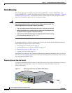
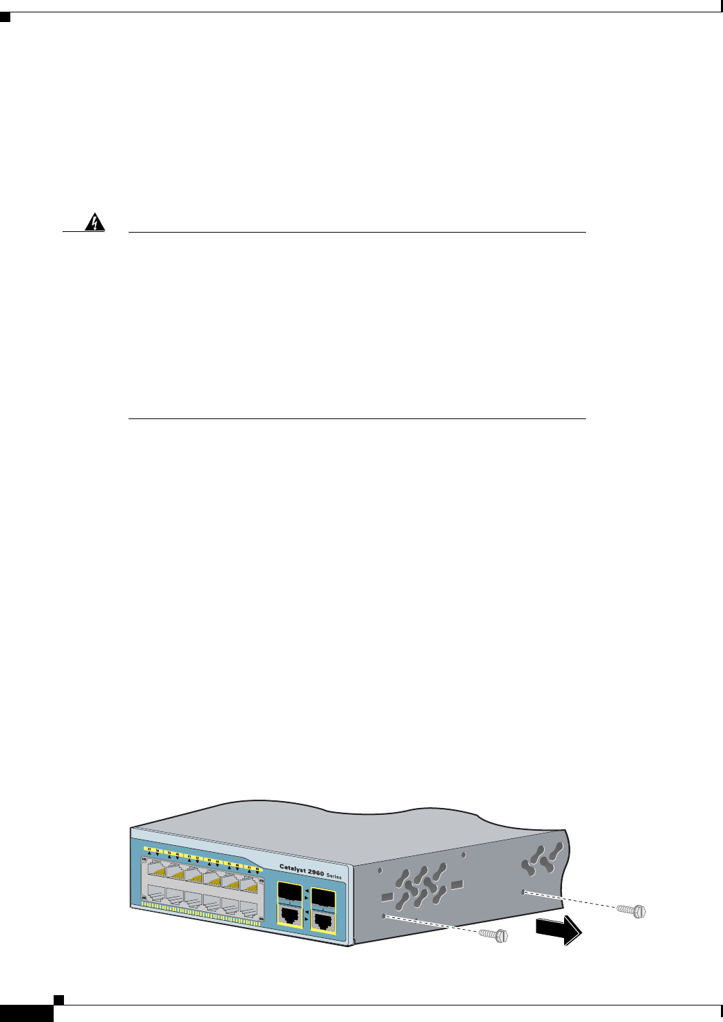
If you plan to install the switch in a rack, you must first remove screws in the switch chassis so that you
can attach the mounting brackets.
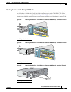
Figure 2-1 shows how to remove the chassis screws in a
Catalyst 2960 switch.
Figure 2-1 Removing Screws from the Catalyst 2960 Switch
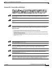
Warning
To prevent bodily injury when mounting or servicing this unit in a rack, you
must take special precautions to ensure that the system remains stable. The
following guidelines are provided to ensure your safety:
• This unit should be mounted at the bottom of the rack if it is the only unit in the rack.
• When mounting this unit in a partially filled rack, load the rack from the bottom to the
top with the heaviest component at the bottom of the rack.
• If the rack is provided with stabilizing devices, install the stabilizers before mounting
or servicing the unit in the rack.
Statement 1006
137072
1X
11X


