


2-5
Catalyst 2960 Switch Hardware Installation Guide
OL-7075-05
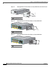
Chapter 2 Switch Installation (24- and 48-Port Switches)
Preparing for Installation
These standards provide guidelines for acceptable working environments and acceptable levels of
suspended particulate matter:
• Network Equipment Building Systems (NEBS) GR-63-CORE
• National Electrical Manufacturers Association (NEMA) Type 1
• International Electrotechnical Commission (IEC) IP-20
This precaution applies to all Catalyst 2960 switches except for the Catalyst 2960-8TC, 2960G-8TC, and
2960PD-8TT-L switches.
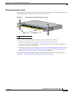
Installation Guidelines
This section does not apply to the Catalyst 2960-8TC, 2960G-8TC, and 2960PD-8TT-L switches. For
information applicable to those switches, see
Chapter 3, “Switch Installation (8-Port Switches).”
When you determine where to place the switch, be sure to observe these requirements:
• For 10/100/1000 ports, cable lengths from the switch to connected devices must be no longer than
328 feet (100
meters).
• The cables meet the specifications in Table A-1 on page A-5, which lists the cable specifications for
1000BASE-X and 100BASE-X SFP modules available for the Catalyst 2960 switch. Catalyst 2960
switch SFP
ports can use both GLC-GE-100XX and GLC-FE-100XX SFP modules.
When you use shorter lengths of single-mode fiber cable, you might need to insert an inline optical
attenuator in the link to avoid overloading the receiver.
When the fiber-optic cable span is less than 15.43 miles (25 km), you should insert a 5-decibel (dB)
or 10-dB inline optical attenuator between the fiber-optic cable plant and the receiving port on the
1000BASE-ZX SFP module at each end of the link.
• The operating environment must be within the ranges listed in Appendix B, “Technical
Specifications.”
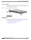
• Clearance to front and rear panels meets these conditions:
–
You can easily read the front-panel indicators.
–
Access to ports is sufficient for unrestricted cabling.
–
The rear-panel power connector is within reach of an AC power receptacle.
• Cabling is away from sources of electrical noise, such as radios, power lines, and fluorescent
lighting fixtures. Make sure the cabling is safely away from other devices that might damage the
cables.
• Airflow around the switch and through the vents is unrestricted.
• Temperature around the unit does not exceed 113°F (45°C).
If the switch is installed in a closed or multirack assembly, the temperature around it might be
greater than normal room temperature.