


2-21
Catalyst 2960 Switch Hardware Installation Guide
OL-7075-05
Chapter 2 Switch Installation (24- and 48-Port Switches)
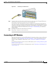
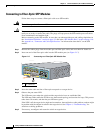
Connecting to SFP Modules
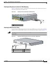
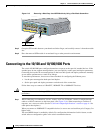
Connecting to 1000BASE-T SFP Modules
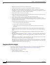
Follow these steps to connect a Category 5 (or higher) cable to a 1000BASE-T SFP module:
Caution To prevent ESD damage, follow your normal board and component handling procedures.
Step 1 Insert one end of the cable into the SFP module port (see Figure 2-18). When connecting to servers,
workstations, and routers, insert a four twisted-pair, straight-through cable in the RJ-45 connector. When
connecting to switches or repeaters, insert a four twisted-pair, crossover cable.
Note When connecting to a 1000BASE-T device, be sure to use a four twisted-pair, Category 5 or
higher cable.
Note The auto-MDIX feature is enabled by default. For configuration information for this feature, see
the switch software configuration guide or the switch command reference.
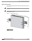
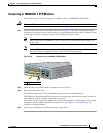
Figure 2-18 Connecting to a 1000BASE-T SFP Module
Step 2 Insert the other cable end in an RJ-45 connector on a target device.
Step 3 Observe the port status LED.
The LED turns green when the switch and the target device have an established link.
The LED turns amber while the STP discovers the network topology and searches for loops. This process
takes about 30 seconds, and then the port LED turns green.
If the LED is off, the target device might not be turned on, there might be a cable problem, or there might
be problem with the adapter installed in the target device. See
Chapter 4, “Troubleshooting,” for
solutions to cabling problems.
Step 4 If necessary, reconfigure and restart the switch or target device.
1 RJ-45 connector
137168
1X
11X
1
1