


2-15
Catalyst 2960 Switch Hardware Installation Guide
OL-7075-05
Chapter 2 Switch Installation (24- and 48-Port Switches)
Installing and Removing SFP Modules
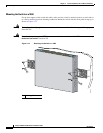
After the switch is mounted on the wall, do these tasks to complete the installation:
• Power on the switch. See the “Verifying Switch Operation” section on page 2-7.
• Connect to a 10/100 or 10/100/1000 port, and run Express Setup. See the Catalyst 2960 Switch
Getting Started Guide for instructions.
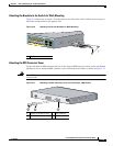
• Connect to the front-panel ports. See the “Connecting to the 10/100 and 10/100/1000 Ports” section
on page 2-18, the “Connecting to SFP Modules” section on page 2-19, and the “Connecting to a
Dual-Purpose Port” section on page 2-22 to complete the installation.
For configuration instructions about using the CLI setup program, go to Appendix C, “Configuring the
Switch with the CLI-Based Setup Program.”
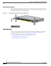
Table- or Shelf-Mounting
This section applies to all switches except the Catalyst 2960-8TC-L, Catalyst 2960G-8TC-L, and
Catalyst 2960PD-8TT-L switches. For
information applicable to those switches, see Chapter 3, “Switch
Installation (8-Port Switches).”
Follow these steps to install the switch on a table or shelf:
Step 1 Locate the adhesive strip with the rubber feet in the mounting-kit envelope. Attach the four rubber feet
to the recessed areas on the bottom of the unit.
Step 2 Place the switch on the table or shelf near an AC power source.
After the switch is mounted on the table, do these tasks to complete the installation:
• Power on the switch. See the “Verifying Switch Operation” section on page 2-7.
• Connect to a 10/100 or 10/100/1000 port, and run Express Setup. See the Catalyst 2960 Switch
Getting Started Guide for instructions.
• Connect to the front-panel ports. See the “Connecting to the 10/100 and 10/100/1000 Ports” section
on page 2-18, “Connecting to SFP Modules” section on page 2-19 and the “Connecting to a
Dual-Purpose Port” section on page 2-22 to complete the installation.
For configuration instructions about using the CLI setup program, go to Appendix C, “Configuring the
Switch with the CLI-Based Setup Program.”
Note When the connectors are not being used, replace the dust covers on them for protection.
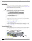
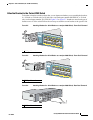
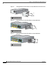
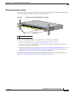
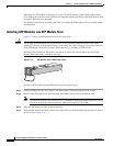
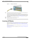
Installing and Removing SFP Modules
These sections describe how to install and remove SFP modules. SFP modules are inserted into SFP
module slots on the front of the Catalyst 2960 switches. These field-replaceable modules provide the
uplink optical interfaces, laser send (TX) and laser receive (RX).
You can use any combination of SFP modules. Refer to the Catalyst 2960 switch release notes for the
list of SFP modules that the Catalyst 2960 switch supports. Each SFP module must be of the same type
as the SFP module on the other end of the cable, and the cable must not exceed the stipulated cable length
for reliable communications. See the
“SFP Module Cable Specifications” section on page A-4 for cable