


3-12
Catalyst 2960 Switch Hardware Installation Guide
OL-7075-05
Chapter 3 Switch Installation (8-Port Switches)
Installing the Switch
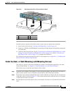
Wall-Mounting (with Mounting Screws)
This section is specific to the Catalyst 2960 8-port switches. For information applicable to the other
Catalyst 2960 switches, see
Chapter 2, “Switch Installation (24- and 48-Port Switches).”
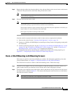
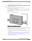
The steps in this section show how to mount the switch with the front panel facing down (as shown in
Figure 3-5 on page 3-12 and Figure 3-6 on page 3-13.)
Note Do not wall-mount the switch with its front panel facing up or sideways. According to safety regulations,
wall-mount the switch with its front panel facing down to prevent airflow restriction and to provide
easier access to the cables.
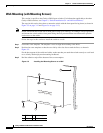
Follow the steps in this section to install the switch to a wall:
Step 1 Locate the screw template. The template is used to align the mounting screw holes.
Step 2 Position the screw template so that the two side-by-side slots face toward the floor, as shown in
Figure 3-5.
For the best support of the switch and cables, make sure that you attach the switch securely to a wall stud
or to a firmly attached plywood mounting backboard.
Step 3 Peel the adhesive strip off the bottom of the screw template.
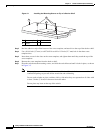
Figure 3-5 Installing the Mounting Screws on a Wall
1 Wall 3 Screw template
2 Screws
CABLE SIDE ENTRY
THIS SIDE AWAY FROM
MOUNTING SURFACE
2
3
2
2
1
157828