


2-13
Catalyst 2960 Switch Hardware Installation Guide
OL-7075-05
Chapter 2 Switch Installation (24- and 48-Port Switches)
Installing the Switch
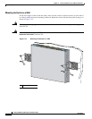
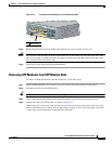
Attaching the Brackets to the Switch for Wall-Mounting
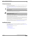
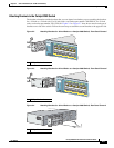
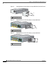
Figure 2-10 shows how to attach a 19-inch bracket to one side of the switch. Follow the same steps to
attach the second bracket to the opposite side.
Figure 2-10 Attaching the 19-inch Brackets for Wall-Mounting
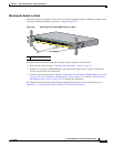
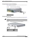
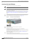
Attaching the RPS Connector Cover
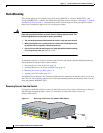
If your switch has an RPS connector and you are not using an RPS with your switch, use the two Phillips
pan-head screws to attach the RPS
connector cover to the back of the switch, as shown in Figure 2-11.
Warning
If an RPS is not connected to the switch, install an RPS connector cover on the back of the switch.
Statement 265
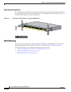
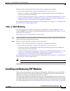
Figure 2-11 Attaching the RPS Connector Cover on the Catalyst 2960 Switch
1 Phillips truss-head screws
1
137088
1
X
1
1
X
1 Phillips pan-head screws 3 RPS connector
2 RPS connector cover
C
O
N
S
O
L
E
21
3
137082