


3-7
Catalyst 2960 Switch Hardware Installation Guide
OL-7075-05
Chapter 3 Switch Installation (8-Port Switches)
Installing the Switch
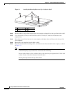
Step 2 Remove the four rubber feet from the adhesive strip, and attach them to the recessed areas on the bottom
of the unit. This prevents the switch from sliding on the desk or shelf.
Note We strongly recommend that you attach the rubber feet. Doing so helps prevent airflow
restriction and overheating.
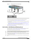
Step 3 Place the switch on the desk or shelf.
Note We strongly recommend that you allow at least 3 inches (7.6 cm) of clearance around the
ventilation openings to prevent airflow restriction and overheating.
Do not stack switches or place switches side-by-side unless they are separated on all sides by at
least 3
inches (7.6 cm) of clearance from each other.
Do not place any items on the top of the switch.
After the switch is mounted on the desk or shelf, do these tasks to complete the installation:
1. Power on the switch. See the “Verifying Switch Operation” section on page 3-6.
2. Connect to a 10/100 or 10/100/1000 port, and run Express Setup. See the switch getting started guide
for instructions.
3. Connect to the front-panel ports. See the “Connecting to the 10/100 and 10/100/1000 Ports” section
on page 2-18, the “Connecting to SFP Modules” section on page 2-19, and the “Connecting to a
Dual-Purpose Port” section on page 2-22 to complete the installation.
For configuration instructions about using the command-line interface (CLI) setup program, go to
Appendix C, “Configuring the Switch with the CLI-Based Setup Program.”
Desk- or Shelf-Mounting (with Mounting Screws)
This section is specific to the Catalyst 2960 8-port switches. For information applicable to the other
Catalyst 2960 switches, see
Chapter 2, “Switch Installation (24- and 48-Port Switches).”
The switch can be secured to a desk or shelf with mounting screws. Follow these steps:
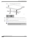
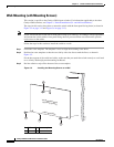
Step 1 Locate the screw template. You can use the template to align the mounting screw holes and also as a
guide to make sure that you install the screws into the desk or shelf with proper clearance.
Step 2 Position the screw template on top of the desk or shelf so that the two side-by-side slots face the front of
the desk or shelf, as shown in
Figure 3-1. This ensures that the power cord faces the rear of the desk or
shelf after the switch is installed.
Note Wait before you attach the screw template to the desk or shelf.