


A-1
Catalyst 2960 Switch Hardware Installation Guide
OL-7075-05
APPENDIX
A
Connector and Cable Specifications
This appendix describes the Catalyst 2960 switch ports and the cables and adapters that you use to
connect the switch to other devices and includes these sections:
• Connector Specifications, page A-1
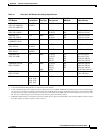
• Cable and Adapter Specifications, page A-4
Connector Specifications
These sections describe the connectors used with the Catalyst 2960 switch:
• 10/100/1000 Ports, page A-1
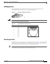
• SFP Module Ports, page A-3
• Dual-Purpose Ports, page A-3
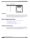
• Console Port, page A-4
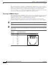
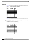
10/100/1000 Ports
The 10/100/1000 Ethernet ports on the Catalyst 2960 switch use standard RJ-45 connectors. Figure A-1
shows the pinout.
Note The auto-MDIX feature is enabled by default. For configuration information for this feature, see the
switch software configuration guide or the switch command reference.
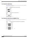
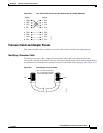
Connecting to 10BASE-T- and 100BASE-TX-Compatible Devices
When connecting the ports to 10BASE-T- and 100BASE-TX-compatible devices, such as servers,
workstations, and routers, you can use a two or four twisted-pair, straight-through cable wired for
10BASE-T and 100BASE-TX.
Figure A-5 shows the two twisted-pair, straight-through cable
schematics. Figure A-7 shows the four twisted-pair, straight-through cable schematics.