


1-13
Catalyst 2960 Switch Hardware Installation Guide
OL-7075-05
Chapter 1 Product Overview
Front Panel Description
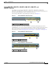
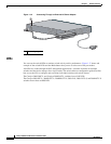
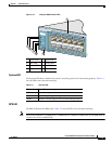
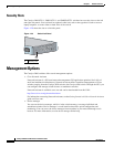
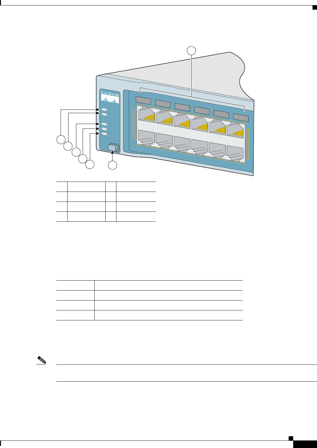
Figure 1-17 Catalyst 2960 Switch LEDs
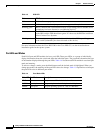
System LED
The System LED shows whether the system is receiving power and is functioning properly. Table 1-2
lists the LED colors and their meanings.
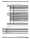
RPS LED
The RPS LED shows the RPS status. Table 1-3 lists the LED colors and their meanings.
Note The Catalyst 2960-8TC-L, 2960G-8TC-L, 2960PD-8TT-L, 2960-24-S, 2960-24TC-S, and 2960-48TC-S
switches do not have an RPS LED.
1 SYST LED 5 Speed LED
2 RPS LED 6 Mode button
3 Status LED 7 Port LEDs
4 Duplex LED
137070
S
Y
S
T
R
P
S
S
T
A
T
D
U
P
L
X
S
P
E
E
D
M
ODE
1X
11X
1X
11X
1
2
3
4
5
6
7
8
9
10
11
12
5
4
7
1
2
3
6
Table 1-2 System LED
Color System Status
Off System is not powered on.
Green System is operating normally.
Amber System is receiving power but is not functioning properly.