


1-17
Catalyst 2960 Switch Hardware Installation Guide
OL-7075-05
Chapter 1 Product Overview
Rear Panel Description
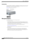
Dual-Purpose Port LEDs
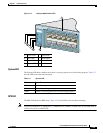
The LEDs on a dual-purpose port show whether an RJ-45 connector is connected to the port, or if an SFP
module is installed in the slot. See the example in
Figure 1-18. You can configure each port as either a
10/100/1000 port through the RJ-45 connector or as an SFP module, but not both at the same time. The
LEDs show how the port is being used (Ethernet or SFP module).
The LED colors have the same meanings as described in Table 1-4 and Table 1-5.
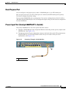
Figure 1-18 Dual-Purpose Port LEDs
Cable Guard for the Catalyst 2960-8TC-L, 2960G-8TC-L, and
2960PD-8TT-L
Switches
You can order an optional cable guard to secure cables to the front of the Catalyst 2960-8TC-L,
2960G-8TC-L, and 2960PD-8TT-L switches and to prevent them from being accidentally removed.
To order a cable guard, contact your Cisco representative using these part numbers:
• CBLGRD-C2960-8TC: Catalyst 2960-8TC-L and Catalyst 2960PD-8TT-L switches
• CBLGRD-C2960G-8TC: Cisco Catalyst 2960G-8TC switch
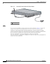
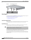
Rear Panel Description
The rear panels on the Catalyst 2960 switches have all or some of these features: an RJ-45 console port,
a fan exhaust, an RPS connector, and an AC power
connector (see Figure 1-19.) These are the
exceptions:
• No RPS connector: Catalyst 2960-8TC-L, 2960G-8TC-L, 2960PD-8TT-L, 2960-24-S,
2960-24TC-S, and 2960-48TC-S.
• No fan: Catalyst 2960-8TC-L, 2960G-8TC-L, and 2960PD-8TT-L. The console port on these
switches is on the front panel rather than on the rear panel.
• AC power adapter input: Catalyst 2960PD-8TT-L switch.
1 RJ-45 connector 3 SFP module port in-use LED
2 RJ-45 port in-use LED 4 SFP module slot
1
41
2 3