


1-14
Catalyst 2960 Switch Hardware Installation Guide
OL-7075-05
Chapter 1 Product Overview
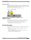
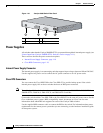
Front Panel Description
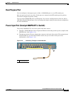
For more information about the Cisco RPS 2300 or the Cisco RPS 675, see the related hardware
installation guide for that power system.
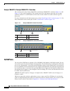
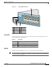
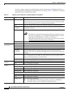
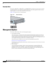
Port LEDs and Modes
Each RJ-45 port and SFP module slot has a port LED. These port LEDs, as a group or individually,
display information about the switch and about the individual ports. The port modes determine the type
of information displayed through the port LEDs.
Table 1-4 lists the mode LEDs and their associated port
mode and meaning.
To select or change a mode, press the Mode button until the desired mode is highlighted. When you
change port modes, the meanings of the port LED colors also change.
Table 1-5 explains how to interpret
the port LED colors in different port modes.
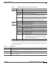
Table 1-3 RPS LED
Color RPS Status
Off RPS is off or not properly connected.
Green RPS is connected and ready to provide back-up power, if required.
Blinking green RPS is connected but is unavailable because it is providing power to another device
(redundancy has been allocated to a neighboring device).
Amber The RPS is in standby mode or in a fault condition. Press the Standby/Active button
on the RPS, and the LED should turn green. If it does not, the RPS fan could have
failed. Contact Cisco Systems.
Blinking amber The internal power supply in a switch has failed, and the RPS is providing power
to the switch (redundancy has been allocated to this device).
Table 1-4 Port Mode LEDs
Mode LED Port Mode Description
STAT Port status The port status. This is the default mode.
DUPLX Port duplex mode The port duplex mode: full duplex or half duplex.
SPEED Port speed The port operating speed: 10, 100, or 1000 Mb/s.