


Connecting the Line Card Cables
Cisco 12008 Gigabit Switch Router Installation and Configuration Guide
3-18
To install the network interface cables in the cable-management system and connect the
cables to the line cards, perform the following steps:
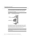
Step 1 Attach an antistatic ESD wrist strap to your wrist; ensure that it makes good
contact with your skin.
Step 2 Insert the equipment end of the wrist strap (the banana jack) into the ESD
connection socket near the lower left corner of the upper card cage. Figure 1-2
shows the location of this socket in the body of the router enclosure.
Step 3 Beginning with the left-most line card in the upper card cage, identify the
interface cables that attach to this line card.
Step 4 Select one interface cable at a time and carefully route it through the left end of
the horizontal cable-management tray and down through the vertical cable-
management bracket to the appropriate line card port.
Note On multiport line cards, the interface cables should be routed down
through the vertical cable-management bracket to the appropriate ports on the
card faceplate, starting with the bottom port and working upward.
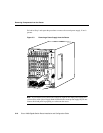
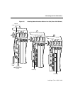
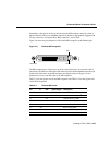
Step 5 Starting with the bottom port (on multiport line cards only), connect the
interface cable to the port (see Figure 3-6a).
Step 6 Carefully press the interface cable into the cable keeper clip nearest the port of
connection (see Figure 3-6b).
Make sure that you do not introduce any sharp bends or kinks into the cable in
securing the cable to the keeper clip.
Step 7 Carefully press the cable into the bottom of the raceway in the vertical cable-
management bracket (see Figure 3-6c).
Again, make sure that you do not introduce any kinks or sharp bends in the
interface cable. The cable should lie in the bottom of the raceway without slack.
Step 8 Repeat the procedure in Step 4 through Step 7 for the remaining ports on the left-
most line card.