


Adding, Removing, or Replacing a DC-Input Power Supply
Cisco 12008 Gigabit Switch Router Installation and Configuration Guide
7-30
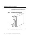
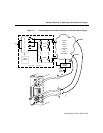
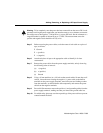
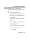
To remove the plastic safety shield (see Figure 7-7), take the following actions:
(a) Loosen the knurled thumb wheel on the bottom left standoff that secures
the safety shield to the power supply faceplate.
(b) Grasp the safety shield and move it to the right and obliquely upward,
positioning the shield so that it can be freed from the three standoffs on the
power supply faceplate.
(c) Remove the shield from the standoffs and set it aside temporarily.
Warning To be completely sure that power has been removed from the source DC circuit
that is presently servicing the power supply, use a voltmeter to measure the voltage across
the negative (–) and positive (+) source DC leads on the power supply. Set the voltmeter to
a range that makes it capable of measuring up to 75 VDC. The measurement across the
positive and negative leads should be zero (0) volts.
Step 5 Before removing the power cables, write the name of each cable on a piece of
tape, as follows:
• Ground
• + (positive)
• – (negative)
Step 6 Attach each piece of tape to the appropriate cable to identify it for later
reconnection.
Step 7 Remove the power cables from the power supply terminals; strictly observe the
following order in removing the cables:
(a) – (negative)
(b) + positive)
(c) Ground