


Removing and Replacing the RP
Cisco 12008 Gigabit Switch Router Installation and Configuration Guide
7-54
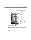
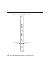
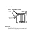
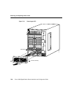
Figure 7-15 Removing the RP (Cisco 12012 Shown)
Installing the RP
As noted in the preceding section, Figure 7-15 illustrates an RP being removed from a
Cisco 12012. For purposes of the RP installation procedure presented in this section, it is
assumed that you will be performing the reverse of the procedure illustrated in Figure 7-15,
but in the context of the Cisco 12008. It is also assumed that you will be installing the RP
in slot 0 of the upper card cage of the Cisco 12008.
S
LO
T-0
GIGABIT ROUTE PROCESSOR
S
LO
T-1
C
OLL
LINK
TX
RX
R
J-45
MII
RE
SET
AUX
C
O
N
S
O
L
E
EJECT
A
C
T
I
V
E
0
C
A
R
R
I
E
R
R
X
P
K
T
A
C
T
I
V
E
1
C
A
R
R
I
E
R
R
X
P
K
T
A
C
T
I
V
E
2
C
A
R
R
I
E
R
R
X
P
K
T
A
C
T
I
V
E
3
C
A
R
R
I
E
R
R
X
P
K
T
Q OC-3/STM-POS
A
C
T
I
V
E
0
C
A
R
R
I
E
R
R
X
C
E
L
L
OC-12/STM-4 ATM
OC-12/STM-4 POS
A
C
T
I
V
E
0
C
A
R
R
I
E
R
R
X
C
E
L
L
ACO/LT
ALARM 1 ALARM 2
ALARM
C
SC
0
FAIL
1
0
1
2
ENABLE
D
CRIT
ICAL
MAJOR
MINOR
SF
C
S
L
O
T
-0
GIGABIT ROUTE PROCESSOR
S
L
O
T
-1
C
O
LL
LIN
K
T
X
R
X
R
J-45
M
II
R
E
S
E
T
A
U
X
C
O
N
S
O
L
E
E
JE
C
T
H10704
Loosen
captive
screws
GRP
Pivot ejector
levers away
from card to
unseat card
Grasp card carrier to
slide card out of slot
a
c
b