


Connecting an External Alarm Monitoring Facility
Cisco 12008 Gigabit Switch Router Installation and Configuration Guide
3-34
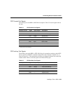
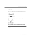
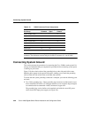
Table 3-9 lists IEEE 802.3u physical characteristics for 100BASE-TX.
Table 3-9 IEEE 802.3u Physical Characteristics
Connecting an External Alarm Monitoring Facility
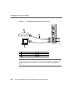
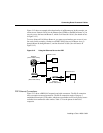
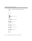
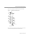
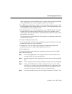
The clock and scheduler card (CSC) incorporates a 25-pin D-sub connector on the card
faceplate (see Figure 3-16) that enables you to attach a site-wide external alarm monitoring
facility to the Cisco 12008. This facility is described in Chapter 1 in the section entitled
“Housekeeping and Alarm Monitoring Functions of the CSC.”
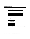
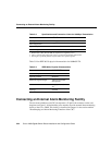
Table 3-8 Specifications and Connection Limits for 100-Mbps Transmission
Parameter RJ-45
Cable specification Category 5
1
UTP, 22 to 24 AWG
2
1. EIA/TIA-568 or EIA-TIA-568 TSB-36 compliant. Not supplied by Cisco.
2. AWG = American Wire Gauge. This gauge is specified by the EIA/TIA-568 standard.
Cable length (max) —
Segment length (max) 328 feet (100 m) for 100BASE-TX
Network length (max) 656 feet (200 m)
3
(with 1 repeater)
3. This length is specifically between any two stations on a repeated segment.
Parameter 100BASE-TX
Data rate (Mbps) 100
Signaling method Baseband
Maximum segment length 100 m between DTE
1
and repeaters
1. DTE = data terminal equipment.
Media Category 5 UTP (for RJ-
45)
Topology Star/Hub