


Adding, Removing, or Replacing an AC-Input Power Supply
Cisco 12008 Gigabit Switch Router Installation and Configuration Guide
7-10
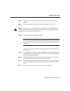
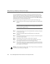
Caution To prevent damage to the blind-mating connector at the rear of the power supply,
do not use excessive speed or force when inserting the power supply into the bay.
Note All necessary electrical connections between the power supply and the backplane
are accomplished automatically by means of the blind-mating connector at the rear of the
power supply.
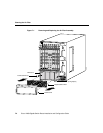
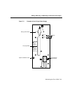
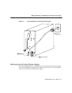
Step 7 Using a 1/4-inch flat-blade screwdriver, tighten the captive installation screw on
the faceplate of the power supply (see Figure 7-3).
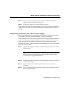
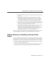
Step 8 Connect the source AC power cord to the AC receptacle on the power supply
faceplate (see Figure 7-4a). Secure the bail latch over the source AC power cord
(see Figure 7-4b).
Step 9 Connect the other end of the source AC power cord to its power source (see
Figure 7-4c).
Step 10 Set the rotary power switch on the new AC-input power supply to the ON (1)
position.
To verify that the new AC-input power supply is operating properly, proceed to the section
entitled “Verifying the Installation of an AC-Input Power Supply.”