


Installing a Cisco 12008 3-25
Connecting Route Processor Cables
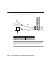
Depending on the type of media you use between the MII receptacle and your switch or
hub, the network side of your 100-Mbps transceiver should be appropriately equipped with
ST-type connectors (for optical fiber), BNC connectors, and so forth.
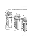
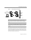
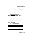
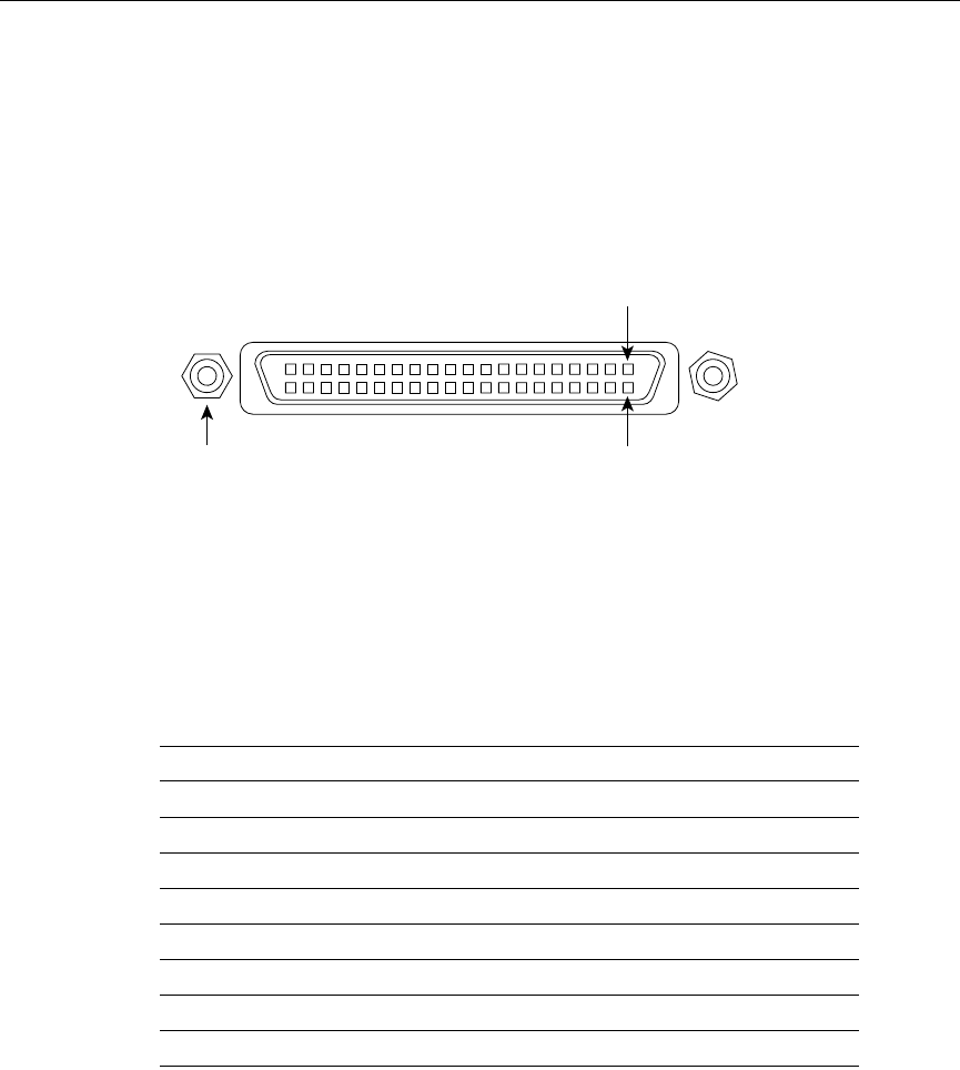
Figure 3-9 shows the pin orientation of the female MII receptacle on the Ethernet port.
Figure 3-9 Ethernet MII Receptacle
The MII receptacle uses 2-56 screw-type locks, called jackscrews, to secure the cable or
transceiver to the MII port. MII cables and transceivers have knurled thumbscrews that you
fasten to the jackscrews on the MII connector and tighten with your fingers. Use the
jackscrews to secure your MII cable to the MII receptacle.
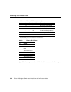
Table 3-3 lists the signals used on the MII receptacle, and Table 3-4 lists the signals used
on the RJ-45 receptacle.
Table 3-3 Ethernet MII Pinout
Pin
1
In Out Input/Output Description
14–17 – Yes – Transmit Data (TxD)
12 Yes –– Transmit Clock (Tx_CLK)
2
11 – Yes – Transmit Error (Tx_ER)
13 – Yes – Transmit Enable (Tx_EN)
3 – Yes – MII Data Clock (MDC)
4–7Yes–– Receive Data (RxD)
9Yes–– Receive Clock (Rx_CLK
10 Yes –– Receive Error (Rx_ER)
Jackscrew Pin 21
Pin 1
H6538