


Maintaining the Cisco 12008 7-73
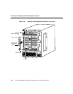
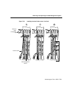
Removing and Replacing the Cable Management System
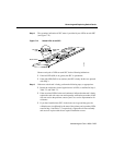
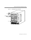
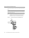
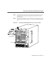
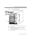
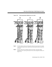
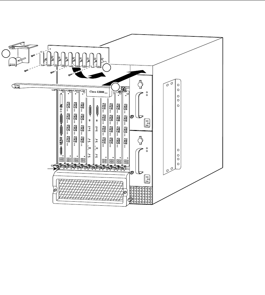
Figure 7-25 Installing a Cable Management Tray
Step 5
Install the end cap onto the chassis by pushing it onto the chassis fasteners (see
Figure 7-25, part 2).
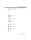
Step 6 Secure the cable-management tray in the recess with the remaining two
installation screws that you set aside in the previous procedure entitled
“Removing a Cable-Management Tray.”
Step 7 Install the top trim piece onto the chassis by pushing it onto the chassis fasteners
(see Figure 7-25, part 3).
2
S
L
O
T
-0
GIGABIT ROUTE PROCESSOR
S
L
O
T
-1
C
O
L
L
L
IN
K
TX
R
X
R
J-4
5
M
II
R
E
S
E
T
A
U
X
C
O
N
S
O
L
E
E
J
E
C
T
C
r
i
t
i
c
a
l
Alarm
Alarms
CSC-8
M
a
j
o
r
M
i
n
o
r
F
a
i
l
S
F
C
F
a
n
F
a
i
l
E
n
a
b
l
e
d
LIN
E
C
AR
D
P
W
R
S
P
LY
ACO/LT
F
a
i
l
C
S
C
E
n
a
b
l
e
d
C
r
i
t
i
c
a
l
Alarm
Alarms
CSC-8
M
a
j
o
r
M
i
n
o
r
F
a
i
l
S
F
C
F
a
n
F
a
i
l
E
n
a
b
l
e
d
L
IN
EC
A
R
D
P
W
R
S
P
L
Y
ACO
/LT
F
a
i
l
C
S
C
E
n
a
b
l
e
d
H11406
Installation screws
ESD socket
1
3