


Installing a Cisco 12008 3-41
Connecting Source Power to the Power Supplies
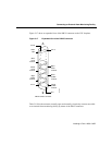
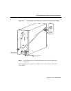
Step 6 Place the grounding lug against the grounding receptacle on the side panel of the
router.
Step 7 Insert two screws through the holes in the grounding lug and the grounding
receptacle. Ensure that the grounding lug will not interfere with other router
hardware or rack equipment.
Step 8 Install the locking washers and nuts; tighten them to secure the grounding lug to
the grounding receptacle.
Step 9 Reinstall the rear access cover on the router. To do so, insert the three tabs of the
access cover into their corresponding slots in rear of the router enclosure; pivot
the cover downward until it rests against the bottom of the router enclosure.
Using a 1/4-inch flat-blade screwdriver, tighten the two captive installation
screws in the bottom of the rear cover to securely fasten the cover in place.
Note If you remove the rear access cover temporarily for any reason, be sure
you reinstall it and secure it in place by firmly tightening the captive installation
screws with a screwdriver. Doing so prevents casual removal of the access cover
without the use of a tool.
Step 10 Prepare the other end of the grounding wire and connect it to an appropriate
grounding point in your site to ensure adequate earth ground for the router.
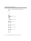
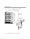
Connecting Source Power to the Power Supplies
This section presents the procedures for applying source power to either an AC-input power
supply or a DC-input power supply. It is assumed that you have already installed one or two
AC-input power supplies or one or two DC-input power supplies, and that your task now is
to connect source power to them.