


Maintaining the Cisco 12008 7-15
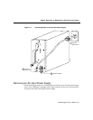
Adding, Removing, or Replacing an AC-Input Power Supply
Note All the necessary electrical connections between the power supply and
the backplane are accomplished automatically by means of the blind-mating
connectors.
Step 14 Using a 1/4-inch flat-blade screwdriver, tighten the captive installation screw on
the power supply faceplate.
Step 15 Connect the source AC power cord to the AC receptacle on the power supply
faceplate.
Step 16 Secure the bail latch over the source AC power cord to secure it in the AC
receptacle.
Step 17 Set the rotary power switch on the new AC-input power supply to the ON (|)
position.
To verify that the new power supply is operating properly, perform the procedure in the
following section.
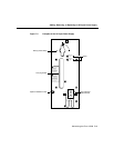
Verifying the Installation of an AC-Input Power Supply
To verify the operation of a newly-installed AC-input power supply, first apply power to the
unit and then observe the status of the LEDs on the power supply faceplate.
To verify the operation of a newly-installed AC-input power supply, perform the following
steps:
Step 1 First, verify that the following conditions have been satisfied:
• The power supply is completely inserted into the bay and secured in place
with its captive installation screw.
• A vacant power supply bay is covered with a blank filler panel to ensure EMI
compliance and the proper flow of cooling air through the router enclosure.
• The source AC power cable is properly connected to the AC receptacle on the
power supply faceplate.