


Maintaining the Cisco 12008 7-47
Removing and Replacing the Fan Trays
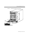
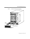
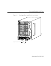
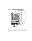
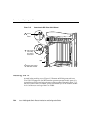
Figure 7-13 Inserting the Power Supply Fan Tray into the Router
Step 4
Using gentle pressure, fully insert the assembly into the bay until the sheet metal
carrier of the fan tray rests against the stop for the captive installation screw.
Step 5 Tighten the captive installation screw on the fan tray faceplate (see Figure 7-13).
To verify that the power supply fan tray is operating properly, proceed to the following
section.
H11401
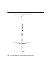
Captive installation screw
S
L
O
T
-0
GIGABIT ROUTE PROCESSOR
S
L
O
T
-1
C
O
LL
L
IN
K
T
X
R
X
R
J
-4
5
M
II
R
E
S
E
T
A
U
X
C
O
N
S
O
L
E
E
J
E
C
T
C
r
i
t
i
c
a
l
Alarm
Alarm
s
CSC-8
M
a
j
o
r
M
i
n
o
r
F
a
i
l
S
F
C
F
a
n
F
a
i
l
E
n
a
b
l
e
d
LIN
EC
A
R
D
PW
R
S
PL
Y
ACO
/LT
F
a
i
l
C
S
C
E
n
a
b
l
e
d
C
r
i
t
i
c
a
l
Alarm
Alarm
s
CSC-8
M
a
j
o
r
M
i
n
o
r
F
a
i
l
S
F
C
F
a
n
F
a
i
l
E
n
a
b
l
e
d
L
IN
E
C
AR
D
P
W
R
SP
L
Y
ACO
/LT
F
a
i
l
C
S
C
E
n
a
b
l
e
d