


Product Overview 1-41
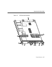
Overview of the Cisco 12008
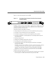
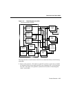
The alphanumeric display LEDs are organized as two rows of four characters each and are
located at one end of the card. These LEDs provide system status and error messages that
are displayed during and after the boot process. The boot process and the content displayed
are controlled by the PRPs MBus module software.
At the end of the boot process, the LEDs are controlled by the Cisco IOS software (via the
MBus), and the content displayed is designated by the Cisco IOS software.
The alphanumeric display LEDs provide information about the following:
• Status of the PRP
• System error messages
• User-defined status and error messages
Note A complete, descriptive list of all system and error messages is located in the Cisco
IOS System Error Messages publications.
Soft Reset Switch
The soft reset switch causes a nonmaskable interrupt (NMI) and places the PRP in ROM
monitor mode. When the PRP enters ROM monitor mode, its behavior depends on the
setting of the PRP software configuration register. (For more information on the software
configuration register, refer to the Configuring the Software Configuration Register section
in Chapter 4) For example, when the boot field of the software configuration register is set
to 0x0, and you press the NMI switch, the PRP remains at the ROM monitor prompt
(
rommon>) and waits for a user command to boot the system manually. But if the boot field
is set to 0x1, the system automatically boots the first IOS image found in the onboard Flash
memory SIMM on the PRP.
Caution The soft reset (NMI) switch is not a mechanism for resetting the PRP and
reloading the IOS image. It is intended for software development use. To prevent system
problems or loss of data, use the soft reset switch only on the advice of Cisco service
personnel.