


Overview of the Cisco 12008
Cisco 12008 Gigabit Switch Router Installation and Configuration Guide
1-8
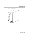
Router Enclosure
The outer shell of the Cisco 12008 is a rigid, sheet metal structure with the following
dimensions:
• Width—17.4 inches (44.6 cm)
• Depth—21.2 inches (54.4 cm)
• Height— 24.8 inches (63.6 cm)
This enclosure, which houses all of the router’s internal components, can be mounted in a
telco rack or a four-post equipment rack, or the enclosure can be used as a freestanding unit.
The design of the enclosure permits front accessibility of all router components. All router
components plug into a backplane that provides operating power for the components and
interconnects them with each other.
The backplane, which is covered by a sheet metal panel that helps to completely enclose
the rear of the router, incorporates a nonvolatile random access memory (NVRAM) module
that stores the backplane serial number for identification and revision control purposes. The
contents of the NVRAM module are accessible from any line card slot.
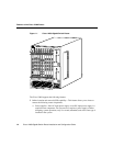
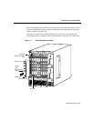
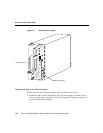
Cable-Management System
The cable-management system provides an orderly and convenient way for you to manage
the network interface cables running to and from the receive and transmit ports of installed
line cards.
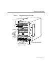
Consisting of a cable-management tray and a vertical cable-management bracket (one
bracket for each installed line card), the cable-management system (see Figure 1-3) secures
the network interface cables neatly in place. The cable management system helps to
optimize optical cable performance by eliminating any kinks or sharp bends in the cables.
Extreme curvatures in optical cables tend to degrade their performance.
The elements of the cable-management system are shown in Figure 1-3 and described
briefly in the following sections:
• Cable-management tray—This tray is attached to the router enclosure above the upper
card cage.