


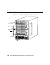

Removing and Replacing the Cable Management System
Cisco 12008 Gigabit Switch Router Installation and Configuration Guide
7-74
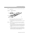
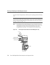
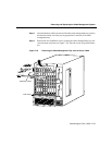
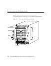
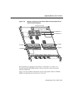
Step 8 Carefully arrange the attached interface cables in the bottom of the cable-
management tray so that they emerge from the tray directly over the intended
line card (see Figure 7-29).
This completes the installation procedure for the Cisco 12008 cable-management tray.
Removing a Cable-Management Bracket
This section tells you how to remove a cable-management bracket from the Cisco 12008.
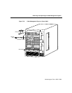
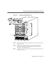
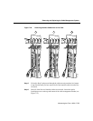
Note Before accessing any of the router’s internal components, put on an antistatic wrist
strap and make sure that it makes adequate contact with your skin. Insert the equipment end
of the wrist strap (the banana jack) into the ESD grounding socket on the lower left edge of
the upper card cage (see Figure 7-24).
To remove a cable-management bracket from a line card, perform the following steps:
Step 1 On a piece of paper, list the current interface cable connections to the port(s) on
each line card.
Note This step may be unnecessary. If the interface cables were originally
installed properly, the length of each cable should leave little question regarding
the port to which it should be connected.
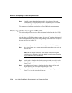
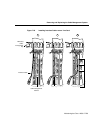
Step 2 Starting with the interface cable for the bottom port on the line card (for cards
with multiple ports), disconnect the cable from the bottom line card port (see
Figure 7-26a).
Step 3 Proceeding upward, remove the interface cable from between all the metal
fingers supporting the cable keeper clips (see Figure 7-26b).
Step 4 Remove the interface cable from the associated cable keeper clip, as shown in
Figure 7-26c). Set the cable aside for later use.