


Installing a Cisco 12008 3-39
Connecting System Ground
These grounding lugs are not available from Cisco Systems; they are common items that
can be obtained from any electrical equipment vendor, such as Panduit.
• Four Phillips head, M6 (metric) machine screws with locking washers and nuts—This
mounting hardware is not available from Cisco Systems; it can be obtained readily from
any commercial electrical equipment vendor.
• Two grounding wires—It is recommended that you use 4 AWG, 0.204-inch (5.18-mm)
diameter wire for grounding purposes. However, you may use a grounding wire of
smaller gauge. The actual wire diameter and length depend on your router location and
the installation environment.
This grounding wire is not available from Cisco Systems; it is commonly available from
commercial cable vendors.
• Number 2 Phillips head screwdriver.
• A 1/4-inch flat-blade screwdriver (to loosen/tighten the captive installation screws at the
bottom of the rear access cover of the router)
• Crimping tool—This tool must be large enough to accommodate the girth of the
grounding lug when you crimp the grounding cable into the lug.
• Wire stripping tool.
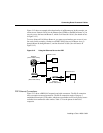
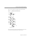
To attach the grounding lug and cable to the grounding receptacle on the Cisco 12008,
perform the following steps:
Step 1 Use a wire-stripping tool to remove approximately 0.75 inch (19 mm) of the
covering from the end of the grounding wire.
Step 2 Insert the stripped end of the grounding wire into the open end of the grounding
lug.
Step 3 Use the crimping tool to secure the grounding wire in place in the grounding lug.
Step 4 Using a 1/4-inch flat-blade screwdriver, remove the rear access cover of the
router. To do so, loosen the two captive installation screws at the bottom of the
cover; pivot the cover up and away from the router to release the three access
cover tabs from their slots. Set the access cover aside temporarily.
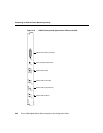
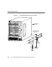
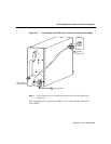
Step 5 Locate the grounding receptacle on the side panel of the router (see Figure 3-18).